
4 layers90 × 100 mm
Harp.device.quad.dac
AllenNeuralDynamics/harp.device.quac
0364: This repository contains the hardware, firmware, and software related to the Harp quad DAC
291 partsMIT

A forearm-focused EMG sensor with 3 channels. Useful for identifying finger or general forearm muscle movements.
EMG2 is an open-source printed circuit board by Janosinth, from the Janosinth/3-Channel_EMG_PCB repository on GitHub. It is a 4-layer board of 103.1 × 63.5 mm with 106 parts on 91 nets, routed with 585 tracks and 86 vias.
It is built around the INA630DDF, MAX6605 and BAT54J, with the SJ-3523-SMT-TR among its other parts. Its parts include 50 resistors, 31 capacitors, 8 diodes, 7 ICs and 5 connectors.


A forearm-focused EMG sensor with 3 channels. Useful for identifying finger or general forearm muscle movements.
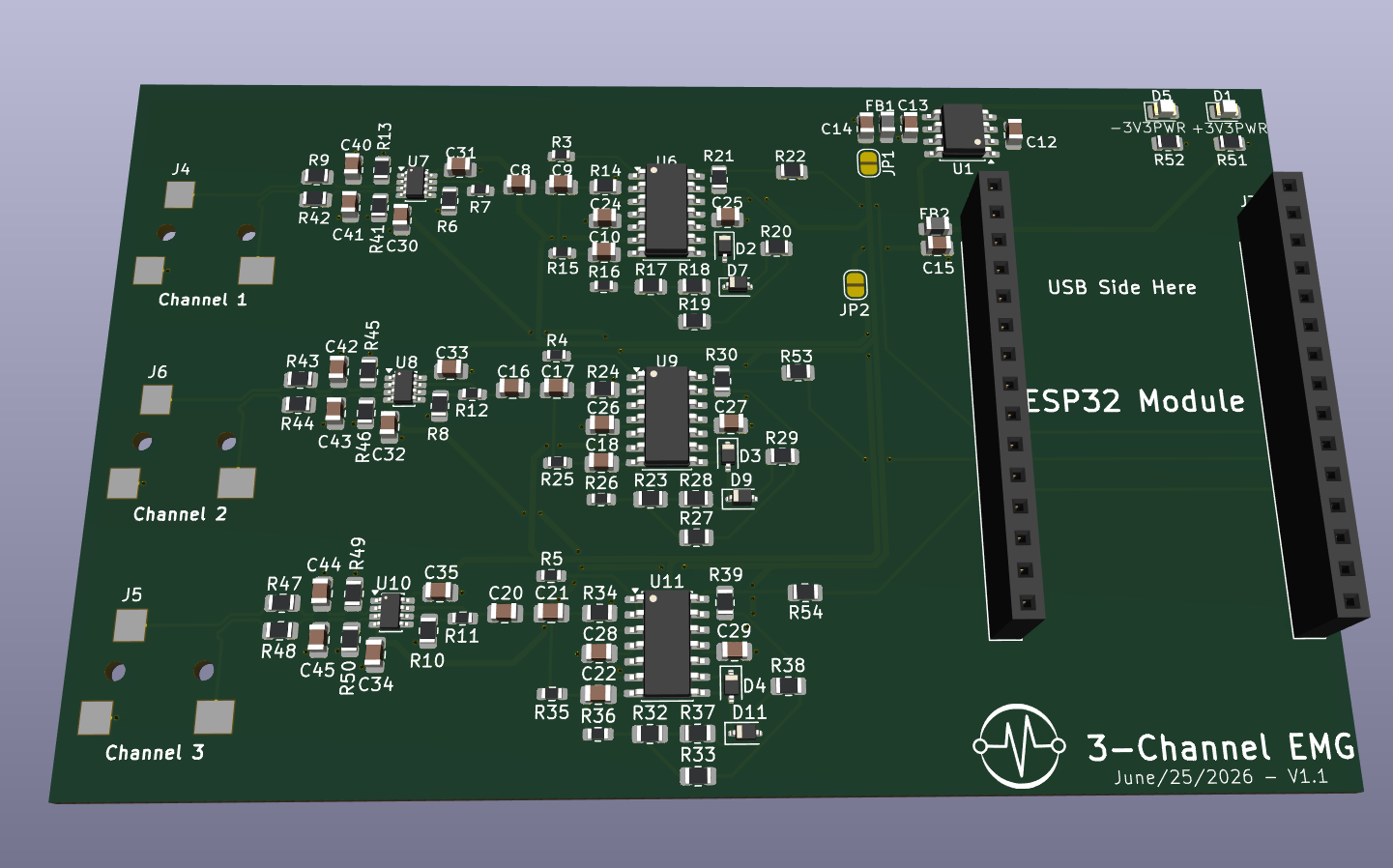
3D Render of PCB
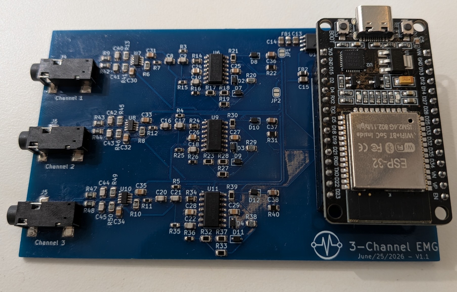
Fully Populated PCB
The design bridges a high-gain, low-noise analog front-end with real-time embedded C++ digital signal processing.
Bio-Amplification: An INA630 instrumentation amplifier interfaces directly with surface electrodes to capture raw muscle action potentials.
Bandpass Filter: Using a TLV9354 operational amplifier, the circuit drives 3 (1 per channel) active bandpass filters with a bandpass of 20 - 500Hz. The bandpass is a combination of a 2nd-order high-pass filter and a first-order low-pass filter.
Active Precision Rectification: The TLV9354 operational amplifier also drives a full active precision wave rectifier. This mathematically eliminates the forward voltage drop typical of passive Schottky diode envelopes, ensuring extremely weak muscle signals are not lost.
Total System Gain: Fixed hardware gain of ~600x designed to pull isolated bio-signals out of the noise floor before hitting the ADC.
Microcontroller: ESP32 operating with a 12-bit ADC configured to ADC_0db (0V - 1.1V range) for maximum microvolt resolution.
Filtering: A real-time C++ Exponential Moving Average (EMA) algorithm processes the raw rectified wave.
Software Scaling: Applies a digital multiplier to map the filtered biological signal to a constrained 0-3.3V logic output for external interfacing or data logging.
Firmware/ — ESP32 C++ code for digital signal processing.
ESP32_Code.ino — Arduino IDE project folder.Hardware/ — KiCad 10.0 project files and custom footprints.
Kicad_Files — All main KiCad files to open the project.EMG2_Stuff.pretty/ — Project-specific dependencies (Custom footprint library (INA630, MAX660, audio jacks).Gerbers/ — Prerendered Gerber files from KiCad files ready for use with JLCPCB manufacturing tolerances.Simulations/ — Analog circuit verification.
EMG_Circuit_Simulation.ms14 — Multisim active filter and precision rectifier simulation files.Video and Image Assets/ — Media and visual documentation.
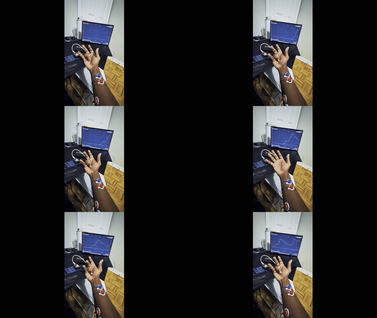
KiCad PCB schematic.png — PCB schematic inside KiCad.Bare PCB.png — Bare manufactured PCB with no soldered components.Full PCB Top Down View.jpg — Top-down view of fully assembled PCB.3D Render.png — 3D render of the PCB in KiCad.Demo Video.gif — GIF of a portion of the demo video.Firmware Deployment:
Clone this repository.
Open Firmware/ESP32_Code.ino in the Arduino IDE.
Select the ESP32 Dev Module board and compile/upload.
Hardware Viewing:
Install KiCad 9.0+.
Open the Hardware/EMG2.kicad_pro file using KiCad, ensuring that the EMG2_Stuff.pretty EMG2.kicad_pro file is under the Hardware file directory.
Note: Ensure the Libraries/EMG2_Stuff.pretty footprint directory is properly linked in your KiCad Footprint Library configuration to prevent "missing footprint" errors when viewing the PCB layout.
| Qty | Value | Footprint | References |
|---|---|---|---|
| 12 | 0.1uF | Capacitor_SMD:C_0805_2012Metric | C24, C25, C26, C27, C28, C29, C30, C31, C32, C33, C34, C35 |
| 12 | 40k | Resistor_SMD:R_0805_2012Metric | R17, R18, R19, R21, R23, R27, R28, R30, R32, R33, R37, R39 |
| 8 | 1k | Resistor_SMD:R_0805_2012Metric | R6, R8, R10, R22, R51, R52, R53, R54 |
| 6 | 10k | Resistor_SMD:R_0805_2012Metric | R9, R42, R43, R44, R47, R48 |
| 6 | 10nF | Capacitor_SMD:C_0805_2012Metric | C8, C9, C16, C17, C20, C21 |
| 6 | 1M | Resistor_SMD:R_0805_2012Metric | R13, R41, R45, R46, R49, R50 |
| 6 | 470pF | Capacitor_SMD:C_0805_2012Metric | C40, C41, C42, C43, C44, C45 |
| 6 | BAT54J | Diode_SMD:D_SOD-323 | D2, D3, D4, D7, D9, D11 |
| 4 | 22uF | Capacitor_SMD:C_0805_2012Metric | C12, C13, C14, C15 |
| 3 | 1.1M | Resistor_SMD:R_0805_2012Metric | R14, R24, R34 |
| 3 | 11k | Resistor_SMD:R_0603_1608Metric | R15, R25, R35 |
| 3 | 18.9k | Resistor_SMD:R_0603_1608Metric | R7, R11, R12 |
| 3 | 1nF | Capacitor_SMD:C_0805_2012Metric | C10, C18, C22 |
| 3 | 20k | Resistor_SMD:R_0805_2012Metric | R20, R29, R38 |
| 3 | 320k | Resistor_SMD:R_0603_1608Metric | R16, R26, R36 |
| 3 | INA630 | Package_TO_SOT_SMD:TSOT-23-8 | U7, U8, U10 |
| 3 | SJ-3523-SMT-TR | EMG2_Stuff:CUI_SJ-3523-SMT-TR | J4, J5, J6 |
| 3 | TL074 | Package_SO:SOIC-14_3.9x8.7mm_P1.27mm | U6, U9, U11 |
| 2 | 569k | Resistor_SMD:R_0603_1608Metric | R4, R5 |
| 2 | 600ohms | Inductor_SMD:L_0805_2012Metric | FB1, FB2 |
| 2 | Conn_01x15_Socket | Connector_PinSocket_2.54mm:PinSocket_1x15_P2.54mm_Vertical | J2, J3 |
| 2 | LED | LED_SMD:LED_0805_2012Metric | D1, D5 |
| 2 | SolderJumper_2_Open | Jumper:SolderJumper-2_P1.3mm_Open_RoundedPad1.0x1.5mm | JP1, JP2 |
| 1 | 569K | Resistor_SMD:R_0603_1608Metric | R3 |
| 1 | LOGO | LOGO | G*** |
| 1 | MAX660 | Package_SO:SOIC-8_3.9x4.9mm_P1.27mm | U1 |
AllenNeuralDynamics/harp.device.quac
0364: This repository contains the hardware, firmware, and software related to the Harp quad DAC


zueblin/Polaron
A DIY drum machine for the teensy microcontroller (hardware / software)


It measures 103.1 × 63.5 mm and has 4 copper layers, 1.6 mm thick.
106 parts, built around the INA630DDF, MAX6605, BAT54J and SJ-3523-SMT-TR. The full list of its parts is on this page, with links to each part's symbol and footprint where PCBKit's library has them.
From the Janosinth/3-Channel_EMG_PCB repository on GitHub, at the commit this page was made from: the board is Hardware/Kicad_Files/EMG2.kicad_pcb and its schematic Hardware/Kicad_Files/EMG2.kicad_sch. PCBKit opens the board in the browser, with nothing to install.
Its repository states no licence, so its author keeps all rights: ask Janosinth before reusing the design.