4 layers120 × 75 mm
Cuttlefish
AllenNeuralDynamics/harp.device.cuttlefish
0414: an octal, TTL input/output device with programmable square wave output.
195 parts

 AllenNeuralDynamics/harp.device.quac
0364: This repository contains the hardware, firmware, and software related to the Harp quad DAC
Harp.device.quad.dac is an open-source printed circuit board by AllenNeuralDynamics, from the AllenNeuralDynamics/harp.device.quac repository on GitHub, published under the MIT licence. It is a 4-layer board of 90 × 100 mm with 291 parts on 177 nets, routed with 1,665 tracks and 423 vias.
It is built around the INA630DDF, TPS65131RGE and W25Q16JVUXIQ, with the RT6150B-33GQW, SN74LVC2T45DCTR and ADUM4160BRW among its other parts. Its parts include 99 resistors, 92 capacitors, 31 ICs, 24 diodes and 18 connectors. It belongs with the audio and music boards and the RP2350 boards of this library.


hardware, firmware, and software source files for a Harp-compatible 4-channel Digital-to-Analog Converter.
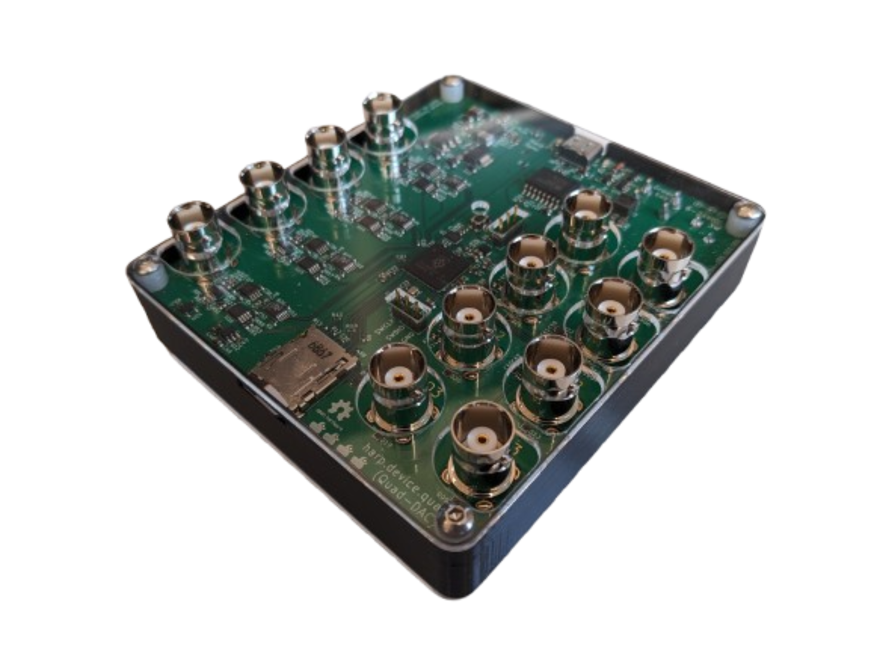
The device features 3 ways to play waveforms: either through the two built-in primitive waveform generators or by playing waveforms pre-uploaded to an SD card.
The Quac board is a fully Harp-protocol-compliant device built on top of the Harp Pico Core.
The harp.device.quac board follows a legacy of many other devices that came before it. For similar devices, have a look at:
Order fully-assembled boards directly from PCBWay.
These printed circuit boards are made on-demand.
There are two ways to generate waveforms: either with one of two primitive waveform generators or by playing files from the SD card. These options are referred to as waveform Players.
Setting up and playing a waveform is a simple process for each Analog Output (AO) channel.
For fully worked examples of the above steps, see the examples in the software folder.
[!NOTE] While waveforms on the SD card will remain on the card until they are deleted, Player settings for any Player do not persist across device power-cycles or resets.
Player Settings are detailed below for each Player.
The following settings are common to each Player.
cycles: number of iterations of the current settings (will probably be 1 in most cases).duration_us: duration in microseconds to play the waveform or 0 to either play-forever (if the source is infinite ie: periodic functions) or play-to-completion (if the source is finite i.e: files on the SD card).update_frequency_hz: rate at which samples are produced (max 500 [KHz]).frequency_hz: sine wave frequency in hertzamplitude_volts: "center-to-peak" amplitude in voltsvertical_shift_volts: vertical shift in voltsnormalized_phase_shift: period shift normalized to -1.0 (max right shift) to 1.0 (max left shift)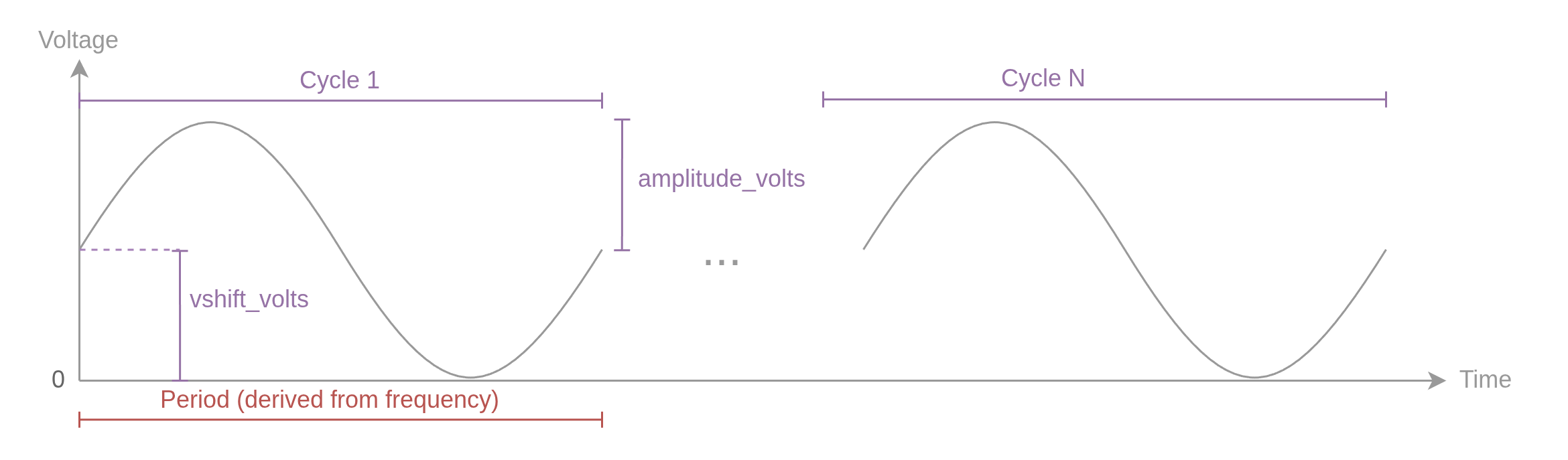
| Setting | Value | Note |
|---|---|---|
cycles | 1 | play the following settings once |
duration_us | 3000000 | play for 3 seconds |
update_frequency_hz | 10000 | rate at which to produce new samples |
frequency_hz | 10 | sine wave frequency |
amplitude_volts | 0.5 | result will be 1 [V] peak-to-peak |
vertical_shift_volts | 0.5 | result will span 0 [V] to 1 [V] |
normalized_phase_shift | 0 | no phase shift |
| Setting | Value | Note |
|---|---|---|
cycles | 1 | |
duration_us | 0 | play forever (until aborted) |
update_frequency_hz | 10000 | |
frequency_hz | 10 | |
amplitude_volts | 0.5 | |
vertical_shift_volts | 0 | |
normalized_phase_shift | 0 |
(Inherits all Common Settings and Sine Player Settings)
ramp_on_us: time in microseconds to rise from lowest to peak value.pulse_width_us: the total pulse width (including ramp-on and ramp-off duration of the waveform in microseconds.ramp_off_us: time in microseconds to fall from peak to lowest value.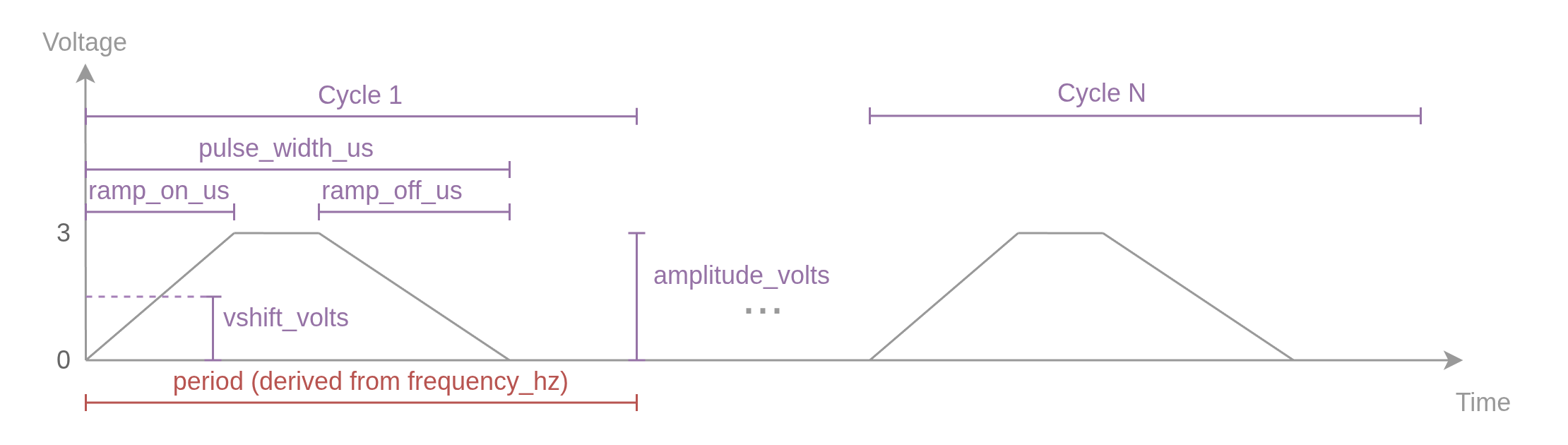
path: filepath on the SD card (32-character limit max)| Setting | Value | Note |
|---|---|---|
cycles | 1 | play the following settings once |
duration_us | 0 | play the file to completion |
update_frequency_hz | 500000 | max update rate (might be different depending on file). |
path | channel_0.bin | assumes this file exists at the top level folder in the SD card |
| Setting | Value | Note |
|---|---|---|
cycles | 3 | loop back and play the entire file 3 times |
duration_us | 0 | |
update_frequency_hz | 500000 | |
path | channel_0.bin |
The quac board reads files in 16-bit little-endian Pulse-Code Modulation (PCM) format. There are a few options for generating waveforms in this format.
It's possible to convert existing audio files to a format compatible with the quac board using ffmpeg.
To upscale an existing *.wav file to a 500KHz update rate, use:
ffmpeg -i example.wav -f u16le -ar 500000 output.rawFor more complicated waveforms that do not derive from an existing audio file, we recommend using numpy.
Here's an example that generates the North American Ringing Tone, which is the sum of a 440Hz and 480Hz sine wave.
import numpy as np

NUM_SAMPLES = int(5e6) # 5 million samples @ 500KSs -> 10 seconds of data.
SAMPLES_PER_SECOND = 500000.
FULL_SCALE_RANGE = (1 << 16) - 1 # 16 bit resolution
SECONDS = NUM_SAMPLES/SAMPLES_PER_SECOND
FILENAME = f"channel_0.bin"

t = np.linspace(0, SECONDS, NUM_SAMPLES)
x = np.zeros(NUM_SAMPLES)

# make sine wave. offset it to uint16 range: 0-65535
for freq in [440, 480]:
    x += (np.sin(2 * np.pi * freq * t)+1)/2 * FULL_SCALE_RANGE/2

# Write result to file in 16-bit little-endian format.
with open(FILENAME, "wb") as file:
x.astype("<u2").tofile(file)Currently waveforms must be uploaded to the SD card manually.
[!WARNING] Power down the device before removing or inserting the SD card.
There are two ways to trigger a configured waveform to play: via software command or through the device's external triggers labeled DI0, DI1, DI2, and DI3.
Before triggering a waveform, you must
For fully worked examples in both Bonsai and Python, see the software examples folder.
By default the device's power-on-reset behavior is setup to: setup external triggers such that pins DIO - DI3 correspond to playing output pins A0 - A3 respectively.
Trigger mapping is configurable! Any input trigger can be configured to trigger any number of outputs. To alter the trigger mapping, you must use software commands through either Bonsai or Python.
During normal operation, up-to-four waveforms stored on the SD card are read (interleaved) at 4MB per second. With the extra overhead of switching between files, the SD card must be able to support read speeds ≥8MB per second. In theory, any Class 10 SD Card formatted in FAT32 format should be compatible.
But since card performance can vary, here's a list of tested cards:
| Vendor | Model |
|---|---|
| Samsung | Pro Plus 8GB Smart Card |
| GIGASTONE | Industrial 8GB MLC |
The following section details how the underlying firmware generates waveforms.
Each channel features a modular approach to dividing up the work of playing waveforms.
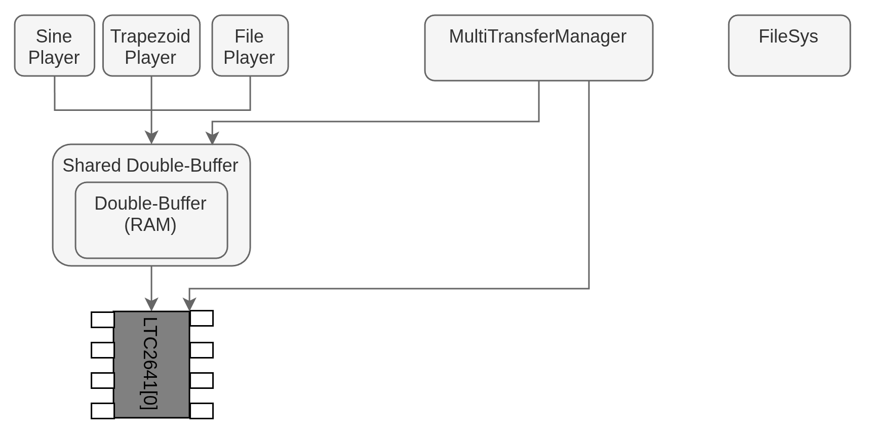
The level closest to the hardware is a driver that wraps a custom PIO program to communicate over SPI to each LTC2641 DAC chip.
The next stage up is a shared double buffer and two DMA channels responsible for ensuring that the driver receives an uninterrupted, steady stream of bytes paced by a DMA Timer setup to match the user-requested playback rate. Inspecting the state of the double buffer is implemented by reading single registers native to the Pico's DMA peripherals to eliminate the need to implement mutex locks to check multiple locations in memory concurrently.
The layer above features one of multiple ways of generating data. These Players are responsible for producing a sequence of bytes up to the limits specified by the user's waveform settings. Each Player is derived from a base class that manages sending data to the corresponding available buffer from the downstream double buffer and manages sequence arming and termination.
In the full architecture, four copies of the above pipeline exist like so:
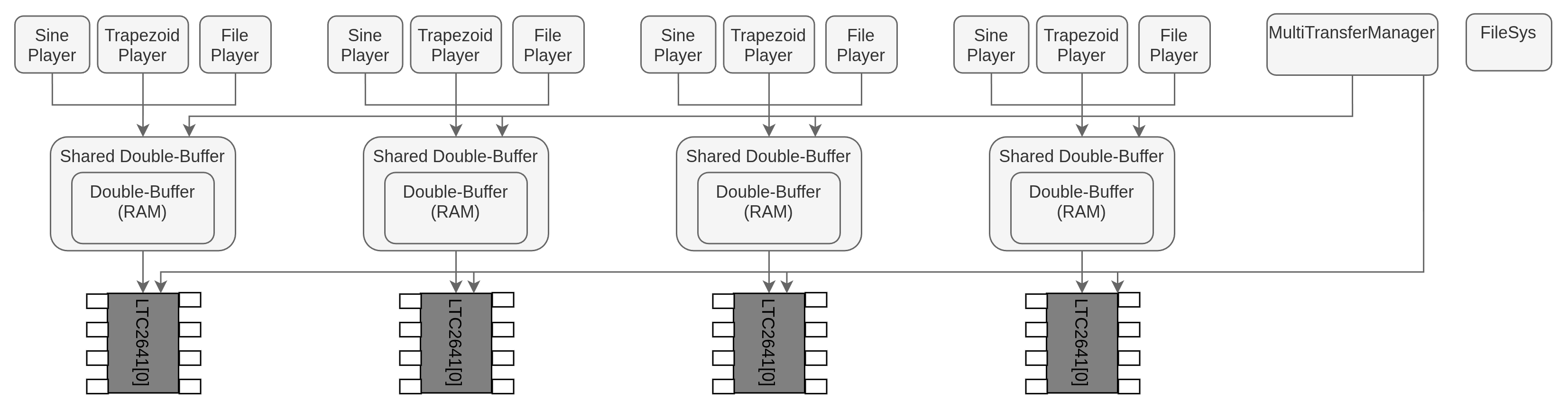
The MultiTransferManager connects to each double buffer and driver and handles triggering an armed transfer, and it guarantees that multiple simultaneous requests to start a transfer occur simultaneously.
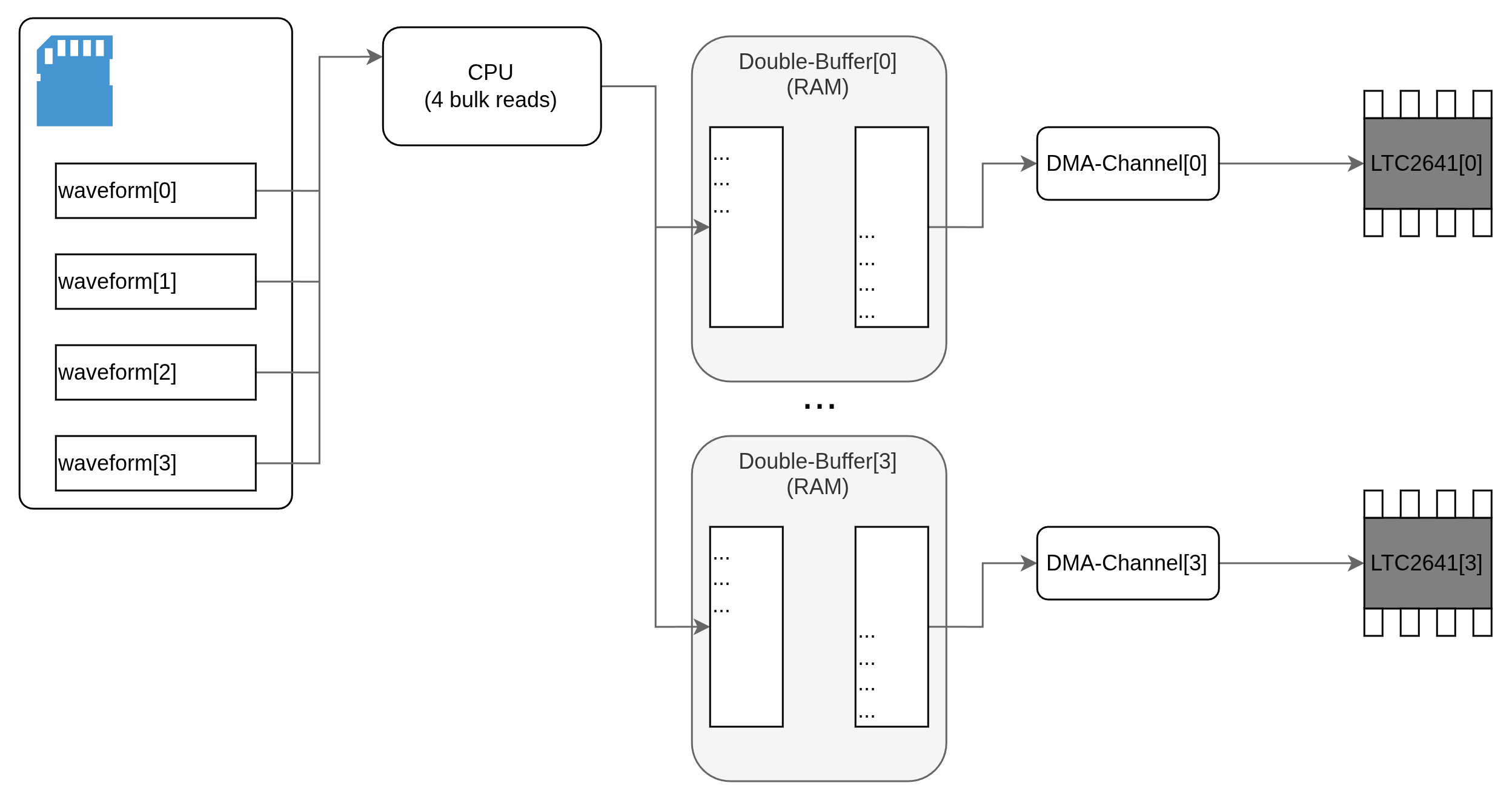
Waveforms are read interleaved from their sources in "chunks" of 16384 samples at a time and then pushed into double buffers such that the resulting output plays waveforms concurrently without interruption.
Buffer size was selected to be large enough such that data from the SD card is can be read faster than it needs to sent to the downstream DAC drivers. This setup was tested in the worst-case scenario where 4 files are being read at once.
A single CPU core is dedicated to this task of reading waveform sources and topping off buffers while the other core handles Harp communication, settings configuration, and waveform start/stop inputs.
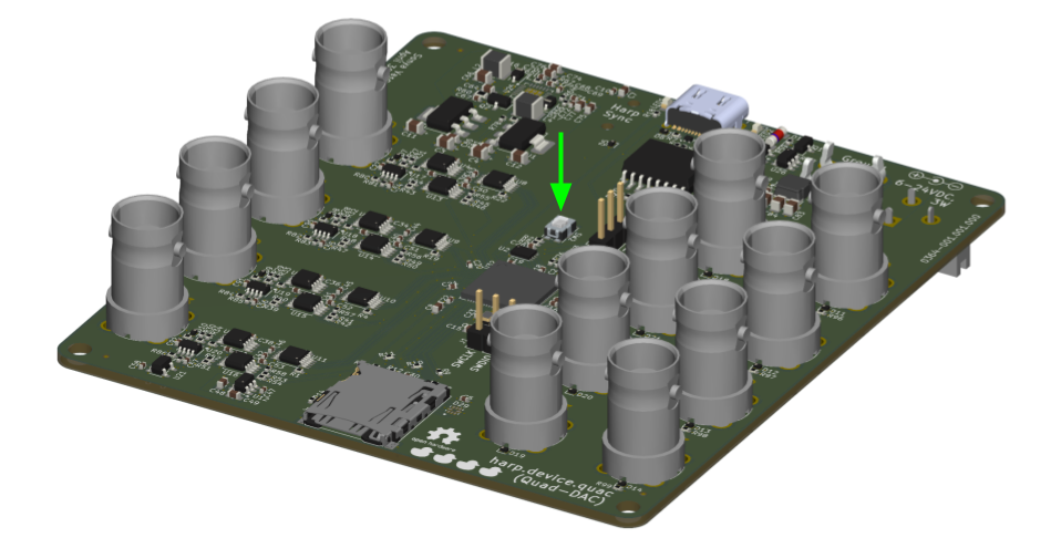
New firmware is available on the Releases Page. To upload new firmware to the device, do the following:
Currently the device has some known limits, most of which are planned to be eclipsed by future firmware releases. This non-comprehensive list includes:
For a full list of issues, head over to the project's issues page.
| Qty | Value | Footprint | References |
|---|---|---|---|
| 53 | 100nF | Capacitor_SMD:C_0402_1005Metric | C10, C16, C17, C18, C19, C20, C21, C22, C23, C25, C26, C27, C29, C30, C31, C32 +37 |
| 21 | 10K | Resistor_SMD:R_0402_1005Metric | R1, R4, R5, R19, R22, R23, R24, R25, R26, R27, R28, R29, R30, R55, R56, R57 +5 |
| 16 | 100K | Resistor_SMD:R_0402_1005Metric | R59, R61, R62, R63, R64, R67, R68, R70, R88, R89, R90, R91, R92, R93, R94, R95 |
| 15 | 1K | Resistor_SMD:R_0402_1005Metric | R2, R17, R18, R40, R41, R44, R45, R48, R49, R52, R53, R80, R82, R84, R86 |
| 14 | VBUS05N1-HD1-G3-08 | Diode_SMD:D_SOD-882 | D1, D2, D3, D4, D5, D6, D11, D12, D13, D14, D18, D19, D20, D21 |
| 12 | Conn_Coaxial | kicad-lib:BNC_AmphenolRF_031-5329-52RFX_Vertical | J6, J7, J8, J9, J10, J11, J12, J13, J15, J16, J17, J18 |
| 10 | 10uF | Capacitor_SMD:C_0603_1608Metric | C15, C63, C65, C74, C75, C76, C77, C79, C80, C81 |
| 8 | 31K6 | Resistor_SMD:R_0402_1005Metric | R39, R42, R43, R46, R47, R50, R51, R54 |
| 7 | 47K | Resistor_SMD:R_0402_1005Metric | R8, R9, R10, R11, R12, R13, R14 |
| 6 | 4.7uF | Capacitor_SMD:C_0603_1608Metric | C1, C2, C8, C13, C14, C64 |
| 6 | 6.8pF | Capacitor_SMD:C_0402_1005Metric | C43, C44, C45, C46, C70, C72 |
| 5 | 100 | Resistor_SMD:R_0603_1608Metric | R60, R72, R73, R74, R75 |
| 5 | 1uF | Capacitor_SMD:C_0603_1608Metric | C7, C24, C28, C48, C49 |
| 5 | 22uF | Capacitor_SMD:C_0805_2012Metric | C66, C73, C83, C84, C85 |
| 5 | 24 | Resistor_SMD:R_0402_1005Metric | R3, R15, R16, R20, R21 |
| 5 | LOGO | LOGO | G***, G***, G***, G***, G*** |
| 4 | 0.05 | Resistor_SMD:R_0402_1005Metric | R35, R36, R37, R38 |
| 4 | 18K9 | Resistor_SMD:R_0402_1005Metric | R81, R83, R85, R87 |
| 4 | 1uF | kicad-lib:C_Polarized_0805_2012Metric | C3, C4, C11, C12 |
| 4 | 30K | Resistor_SMD:R_0402_1005Metric | R31, R32, R33, R34 |
| 4 | INA630 | kicad-lib:TSOT-23-8 | U17, U18, U19, U20 |
| 4 | LMV393IDGKR | kicad-lib:VSSOP-8_3x3mm_P0.65mm_TexasInstruments | U13, U14, U15, U16 |
| 4 | LTC2642 | kicad-lib:MSOP-10_3x3mm_P0.5mm_AnalogDevices | U8, U9, U10, U11 |
| 4 | OPA2810IDGKT | kicad-lib:VSSOP-8_3x3mm_P0.65mm_TexasInstruments | U4, U5, U6, U7 |
| 4 | PESD12VL1BSLAZ | Diode_SMD:D_SOD-882 | D7, D8, D9, D10 |
| 4 | SN74LVC2T45DCTR | kicad-lib:VSSOP-8_2.3x2mm_P0.5mm_TexasInstruments | U22, U23, U30, U31 |
| 3 | Fiducial | Fiducial:Fiducial_0.5mm_Mask1mm | FID1, FID2, FID3 |
| 3 | Si2369DS | Package_TO_SOT_SMD:SOT-23 | Q1, Q2, Q3 |
| 2 | 27 | Resistor_SMD:R_0402_1005Metric | R76, R77 |
| 2 | 4.7uH | Inductor_SMD:L_1210_3225Metric | L2, L4 |
| 2 | 5-146281-3 | Connector_PinHeader_2.54mm:PinHeader_1x03_P2.54mm_Vertical | J1, J2 |
| 2 | 5.1k | Resistor_SMD:R_0402_1005Metric | R6, R7 |
| 2 | CUS10S30,H3F | Diode_SMD:D_SOD-323 | D16, D17 |
| 2 | LED | LED_SMD:LED_0603_1608Metric_Pad1.05x0.95mm_HandSolder | LED1, LED2 |
| 1 | 10nF | Capacitor_SMD:C_0402_1005Metric | C68 |
| 1 | 124 | Resistor_SMD:R_0402_1005Metric | R78 |
| 1 | 13K7 | Resistor_SMD:R_0402_1005Metric | R71 |
| 1 | 1K07 | Resistor_SMD:R_0402_1005Metric | R79 |
| 1 | 1M05 | Resistor_SMD:R_0402_1005Metric | R65 |
| 1 | 1M15 | Resistor_SMD:R_0402_1005Metric | R66 |
| 1 | 2.2uH | Inductor_SMD:L_0603_1608Metric | L3 |
| 1 | 220nF | Capacitor_SMD:C_0402_1005Metric | C71 |
| 1 | 3.3uH | kicad-lib:L_0806_2016Metric | L1 |
| 1 | 39K2 | Resistor_SMD:R_0402_1005Metric | R69 |
| 1 | 4.7nF | Capacitor_SMD:C_0402_1005Metric | C69 |
| 1 | 6.8uH | kicad-lib:L_Bourns-SRP4030FA | L5 |
| 1 | ADUM4160 | Package_SO:SOIC-16W_7.5x10.3mm_P1.27mm | U3 |
| 1 | AudioJack3 | Connector_Audio:Jack_3.5mm_CUI_SJ-3524-SMT_Horizontal | J3 |
| 1 | BZV55B15 | Diode_SMD:D_MiniMELF | D15 |
| 1 | Barrel_Jack_Switch | Connector_BarrelJack:BarrelJack_CUI_PJ-102AH_Horizontal | J14 |
| 1 | ECS-TXO-2016 | Crystal:Crystal_SMD_2016-4Pin_2.0x1.6mm | Xtal1 |
| 1 | LM2940IMPX-12/NOPB | Package_TO_SOT_SMD:SOT-223-3_TabPin2 | U27 |
| 1 | LM337_SOT223 | Package_TO_SOT_SMD:SOT-223-3_TabPin2 | U1 |
| 1 | LMR51430 | Package_TO_SOT_SMD:SOT-23-6 | U29 |
| 1 | Micro_SD_Card_Det_Hirose_DM3AT | Connector_Card:microSD_HC_Hirose_DM3AT-SF-PEJM5 | J5 |
| 1 | MountingHole_Pad | kicad-lib:Terminal_Keystone_779x_EdgeMount_Horizontal | H1 |
| 1 | REF2033 | Package_TO_SOT_SMD:SOT-23-5 | U21 |
| 1 | REF3525 | Package_TO_SOT_SMD:SOT-23-6 | U12 |
| 1 | RP2350_80QFN | kicad-lib:RP2350-QFN-80-1EP_10x10_P0.4mm_EP3.4x3.4mm_ThermalVias | U32 |
| 1 | SPST-NO | kicad-lib:SW_Push_1P1T-SH_NO_Vertical_Wuerth_WS-TASV | SW2 |
| 1 | TPD2EUSB30 | Package_TO_SOT_SMD:Texas_DRT-3 | TVS1 |
| 1 | TPD6E004 | kicad-lib:IC_TPD6E004RSER | D29 |
| 1 | TPS65131RGE | Package_DFN_QFN:VQFN-24-1EP_4x4mm_P0.5mm_EP2.45x2.45mm_ThermalVias | U25 |
| 1 | USB_C_Receptacle_USB2.0 | Connector_USB:USB_C_Receptacle_JAE_DX07S016JA1R1500 | J4 |
| 1 | W25Q16JVUXIQ | Package_SON:Winbond_USON-8-1EP_3x2mm_P0.5mm_EP0.2x1.6mm | U2 |
| 1 | https://github.com/AllenNeuralDynamics/harp.device.quac | project_lib:harp.device.quac | QR***** |
| 1 | rt6150b-33gqw | kicad_component_library:WDFN-10-1EP_2.5x2.5mm_P0.5_EP1.25x2.1mm | U24 |
| 1 | ~ | Package_TO_SOT_SMD:SOT-23-6 | U26 |
The 285 most common of 291 parts.
AllenNeuralDynamics/harp.device.cuttlefish
0414: an octal, TTL input/output device with programmable square wave output.

AllenNeuralDynamics/harp.device.valve-controller
0368: a 16-channel valve controller

AllenNeuralDynamics/harp.device.lickety-split
0360: an ephys-compliant capacitive lick detector

AllenNeuralDynamics/harp.device.treadmill-driver
0326: a Harp-compatible device for controlling an instrumented mouse treadmill

AllenNeuralDynamics/harp.device.sniff-detector
0382: Signal conditioning board for an implanted thermistor

AllenNeuralDynamics/harp.device.environment-sensor
0357: harp-compliant humidity, pressure, and temperature sensor

AllenNeuralDynamics/harp.device.pico-template
an RP2040-based Harp hardware/firmware project template

dennowiggle/Retro-PETER
3.3V Retro computer project => FPGA + RCBUS + CPU boards making a custom system.
It measures 90 × 100 mm and has 4 copper layers, 1.57 mm thick.
291 parts, built around the INA630DDF, TPS65131RGE, W25Q16JVUXIQ and RT6150B-33GQW. The full list of its parts is on this page, with links to each part's symbol and footprint where PCBKit's library has them.
From the AllenNeuralDynamics/harp.device.quac repository on GitHub, at the commit this page was made from: the board is hardware/harp.device.quad.dac.kicad_pcb and its schematic hardware/Block_Diagram.kicad_sch. PCBKit opens the board in the browser, with nothing to install.
Its repository publishes it under the MIT licence: you may reuse it on that licence's terms (keep the author's notice, and for a copyleft licence share your changes alike).