4 layers61.5 × 21 mm
Analog front end
AllenNeuralDynamics/harp.device.lickety-split
0360: an ephys-compliant capacitive lick detector
55 parts5MIT

 AllenNeuralDynamics/harp.device.lickety-split5
0360: an ephys-compliant capacitive lick detector
Harp.device.lickety split is an open-source printed circuit board by AllenNeuralDynamics, from the AllenNeuralDynamics/harp.device.lickety-split repository on GitHub, published under the MIT licence. It is a 4-layer board of 80 × 50 mm with 193 parts on 135 nets, routed with 1,075 tracks and 230 vias.
It is built around the RP2040, ADA4891-1ARZ and ADA4891-2ARZ, with the ADA4891-4ARZ, W25Q16JVUXIQ and RT6150B-33GQW among its other parts. Its parts include 78 capacitors, 70 resistors, 17 ICs, 6 connectors and 4 diodes. It belongs with the RP2040 boards of this library.


An ephys-compliant lick detector based on measured change in capacitance.
You can now order V1.0.0 from PCBWay:
These printed circuit boards are made on-demand.
You will also need:
Once you receive boards, you will need to upload the firmware from the latest release.
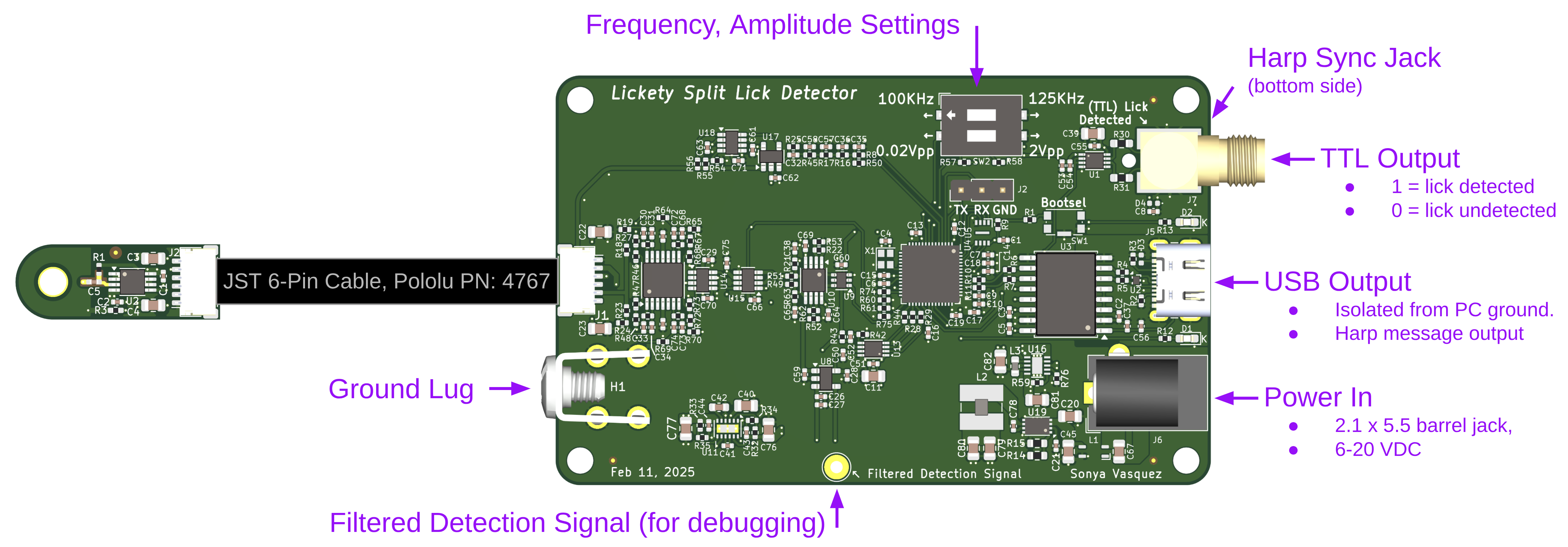
This device has two settings (frequency and amplitude) that are independent of each other. These settings can be set by external switches to designate the state of the board upon power-up.
[!WARNING] Settings can be overwritten through software commands over the Harp interface after the board powers up.
This setting uses the low-amplitude option of the signal.
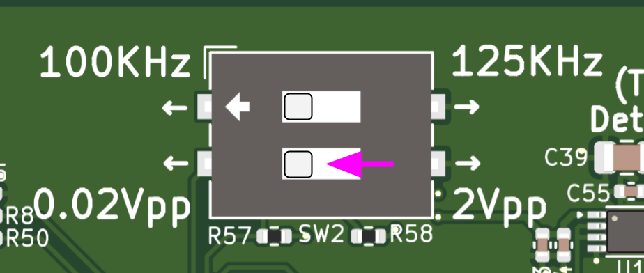
It is necessary to use this setting when interacting with a mouse in an electrophysiology context (i.e: probes inserted in its brain).
Note that this setting, just like Neurpixels Probes, is highly susceptible to noise. Good wiring hygiene (see below) is necessary to eliminate false positives from external noise sources.
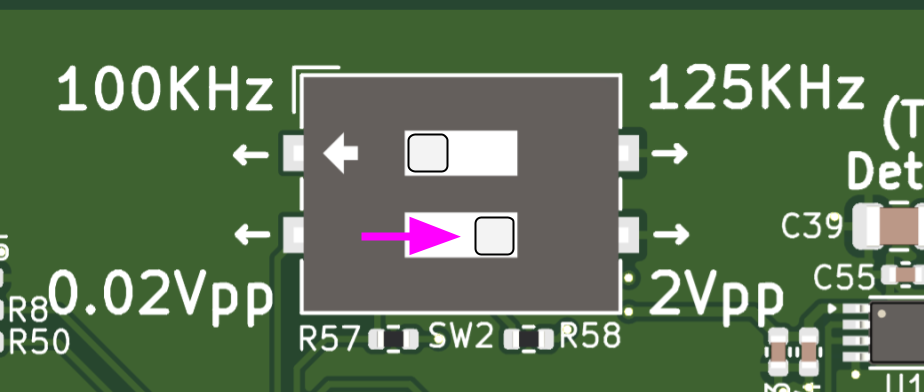
Outside of an electrophysiology context, this setting can be used. It makes the lick detector more immune to most common sources of EMI (valves, etc) because the signal is so much larger in comparison to the noise. This signal can also be run over a much longer cable. (We've used up to 2m!)
There are 3 configurations that will produce valid lick detection readings:
Option A works well if your rig does not have large sources of 60Hz noise.
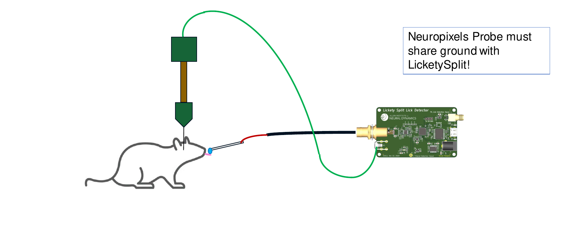
Option B works well if your rig does have large sources of 60Hz noise.
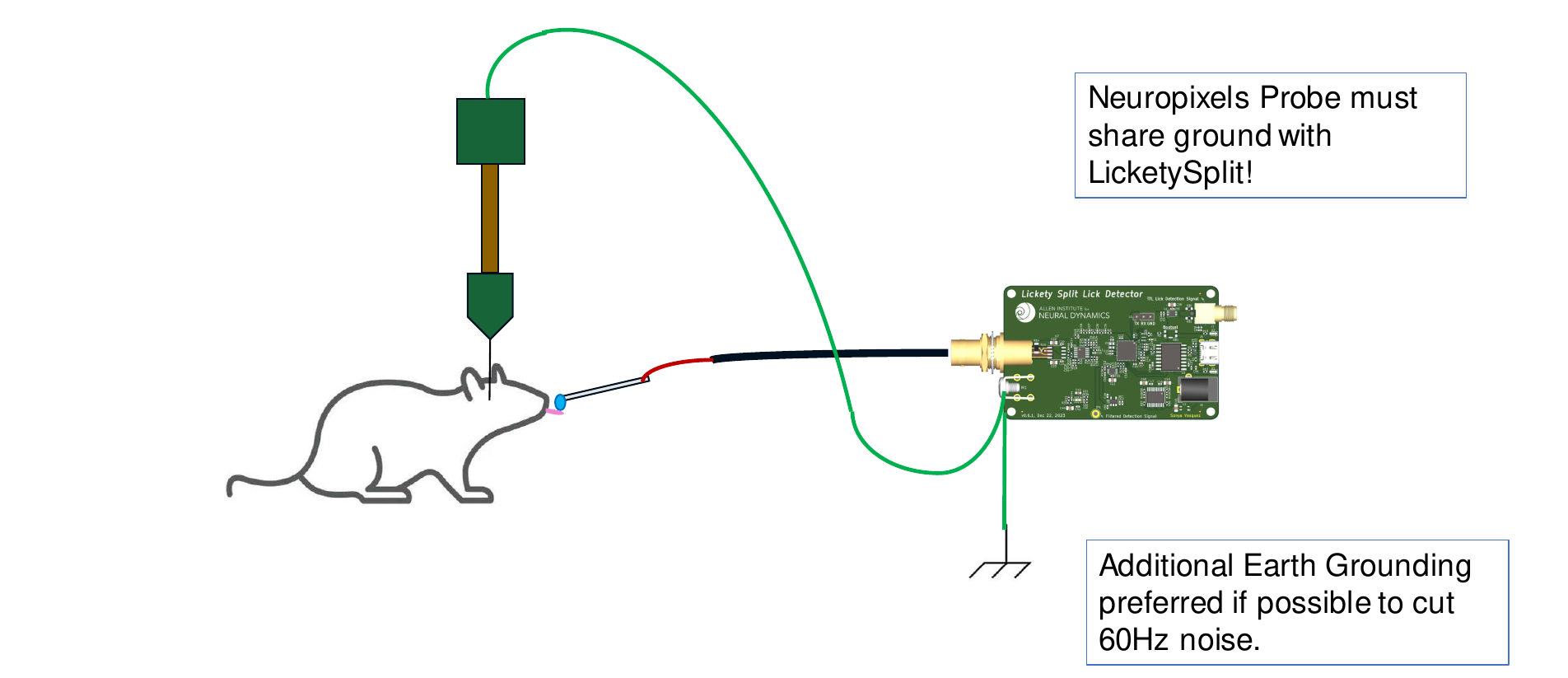
Option C works well if your rig does have large sources of 60Hz noise, but you cannot earth ground it.
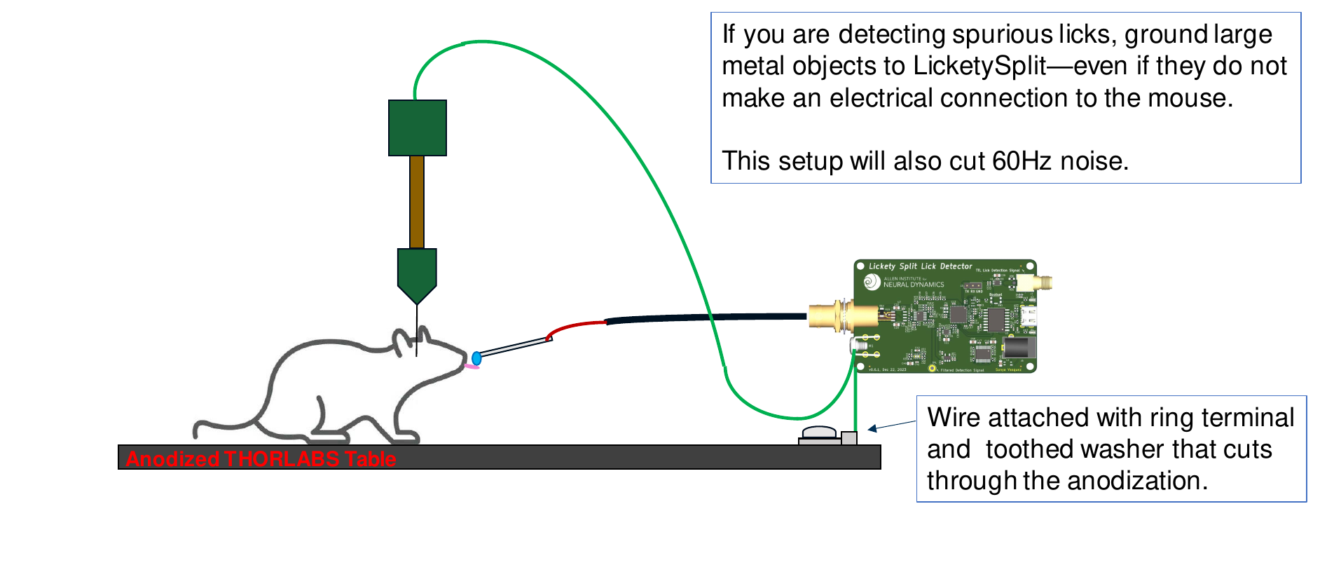
It is critical that (1) both the device and mouse under test are grounded to a common ground and (2) the rig is earth-grounded (i.e: any exposed metal components are connected to earth ground). Otherwise, the device may introduce noise on the Neuropixel probes or produce spurious licks from outside electromagnetic interference.
Multiple lick detectors can be used in the same setup provided that (1) they are grounded correctly (see Electrical Setup), (2) the lick tubes are electrically insulated relative to each other, and (3) the spacing between exposed lick tubes exceeds 4mm. If the spacing between exposed metal lick tubes is less than 4mm, then the antenna noise from one lick detector may affect the other. This phenomenon is called crosstalk, and it can appear in 2 ways.
To fix this issue,
This device detects a threshold change in capacitance. A 100KHz, 10mVpp AC sine wave is played on the tip of a conductive lick spout, (such as McMaster-Carr pn: 89875K271), and the amplitude of the returned waveform is measured every period.
A mouse sharing a ground with this device presents itself as a series resitive and capacitive load. When the mouse's tongue touches the metal tube (or water on the tip of the metal tube), the AC signal passes through the mouse to ground, lowering the amplitude of the returned sine wave below its trigger value, which triggers a lick to be detected. This detection signal is bandpassed in hardware (4th order Butterworth) and the resulting detection signal is lowpassed and compared against a threshold value in firmware to produce a lick/no-lick external trigger output. Overall propagation time through the entire signal chain is less than 1 millisecond.
The detection signal is AC such that repeated contact with the lick tube does not slowly charge the mouse.
Warning: changing the values of these tuning parameters may produce a detection signal that exceeds the <1[ms] detection time guarantee. We suggest ensuring that your setup is electrically grounded correctly first before changing these values.
There are three parameters that can be adjusted related to tuning the lick detection sensitivity. While the starting values should be sufficient for almost all setups, it is (unlikely but) possible that these knobs may need to be adjusted for a particular setup. The four parameters are:
| Qty | Value | Footprint | References |
|---|---|---|---|
| 37 | 100nF | Capacitor_SMD:C_0402_1005Metric | C1, C2, C3, C12, C13, C14, C15, C16, C17, C18, C19, C24, C25, C26, C28, C29 +21 |
| 12 | 10uF | Capacitor_SMD:C_0805_2012Metric | C11, C20, C22, C23, C39, C45, C67, C76, C77, C79, C80, C81 |
| 11 | 1K00 | Resistor_SMD:R_0402_1005Metric | R49, R51, R52, R53, R54, R56, R62, R63, R70, R74, R75 |
| 8 | 1uF | Capacitor_SMD:C_0402_1005Metric | C8, C9, C10, C21, C27, C41, C53, C56 |
| 7 | 4K7 | Resistor_SMD:R_0402_1005Metric | R8, R16, R17, R25, R45, R60, R61 |
| 5 | 100K | Resistor_SMD:R_0402_1005Metric | R55, R59, R66, R71, R76 |
| 5 | 1nF | Capacitor_SMD:C_0402_1005Metric | C32, C35, C36, C57, C58 |
| 4 | 160pF | Capacitor_SMD:C_0402_1005Metric | C30, C31, C68, C72 |
| 4 | 2.2uF | Capacitor_SMD:C_0402_1005Metric | C43, C44, C50, C51 |
| 4 | 24 | Resistor_SMD:R_0402_1005Metric | R4, R5, R6, R7 |
| 3 | 10K | Resistor_SMD:R_0402_1005Metric | R9, R57, R58 |
| 3 | 49.9 | Resistor_SMD:R_0402_1005Metric | R28, R29, R44 |
| 3 | Fiducial | Fiducial:Fiducial_0.5mm_Mask1mm | FID1, FID2, FID3 |
| 3 | MAX4564EKA | Package_TO_SOT_SMD:SOT-23-8 | U14, U15, U18 |
| 2 | 100 | Resistor_SMD:R_0603_1608Metric_Pad0.98x0.95mm_HandSolder | R30, R31 |
| 2 | 120pF | Capacitor_SMD:C_0402_1005Metric | C33, C34 |
| 2 | 127 | Resistor_SMD:R_0402_1005Metric | R42, R43 |
| 2 | 127K | Resistor_SMD:R_0402_1005Metric | R18, R23 |
| 2 | 130pF | Capacitor_SMD:C_0402_1005Metric | C73, C74 |
| 2 | 1K05 | Resistor_SMD:R_0402_1005Metric | R1, R24 |
| 2 | 22uF | Capacitor_SMD:C_0805_2012Metric | C40, C82 |
| 2 | 27 | Resistor_SMD:R_0402_1005Metric | R10, R11 |
| 2 | 51K | Resistor_SMD:R_0402_1005Metric | R34, R35 |
| 2 | 5K1 | Resistor_SMD:R_0402_1005Metric | R2, R3 |
| 2 | 62K | Resistor_SMD:R_0402_1005Metric | R21, R22 |
| 2 | 680 | Resistor_SMD:R_0402_1005Metric | R12, R13 |
| 2 | 8K87 | Resistor_SMD:R_0402_1005Metric | R48, R72 |
| 2 | D_TVS | Diode_SMD:D_0402_1005Metric | D3, D4 |
| 2 | LED | LED_SMD:LED_0603_1608Metric_Pad1.05x0.95mm_HandSolder | D1, D2 |
| 2 | LOGO | LOGO | G1, G3 |
| 1 | 102K | Resistor_SMD:R_0402_1005Metric | R26 |
| 1 | 10K | Resistor_SMD:R_0603_1608Metric | R15 |
| 1 | 10K0 | Resistor_SMD:R_0402_1005Metric | R27 |
| 1 | 10K2 | Resistor_SMD:R_0402_1005Metric | R67 |
| 1 | 113 | Resistor_SMD:R_0402_1005Metric | R47 |
| 1 | 115 | Resistor_SMD:R_0402_1005Metric | R73 |
| 1 | 121K | Resistor_SMD:R_0402_1005Metric | R69 |
| 1 | 133 | Resistor_SMD:R_0402_1005Metric | R46 |
| 1 | 133K | Resistor_SMD:R_0402_1005Metric | R64 |
| 1 | 137 | Resistor_SMD:R_0402_1005Metric | R68 |
| 1 | 15uH | kicad_component_library:L_Wuerth_5.5x5.3mm | L2 |
| 1 | 1K02 | Resistor_SMD:R_0402_1005Metric | R65 |
| 1 | 2.2uH | Inductor_SMD:L_0603_1608Metric | L3 |
| 1 | 2K2 | Resistor_SMD:R_0402_1005Metric | R50 |
| 1 | 300pF | Capacitor_SMD:C_0402_1005Metric | C52 |
| 1 | 4.7uF | Capacitor_SMD:C_0603_1608Metric | C42 |
| 1 | 52K3 | Resistor_SMD:R_0603_1608Metric | R14 |
| 1 | 53K6 | Resistor_SMD:R_0402_1005Metric | R33 |
| 1 | 54K9 | Resistor_SMD:R_0402_1005Metric | R32 |
| 1 | 74LVCH2T45DC | Package_SO:VSSOP-8_2.3x2mm_P0.5mm | U1 |
| 1 | 976 | Resistor_SMD:R_0402_1005Metric | R19 |
| 1 | 97K6 | Resistor_SMD:R_0402_1005Metric | R20 |
| 1 | ADA4891-1 | Package_TO_SOT_SMD:SOT-23-5 | U17 |
| 1 | ADA4891-2 | Package_SO:MSOP-8_3x3mm_P0.65mm | U10 |
| 1 | ADA4891-4 | Package_SO:TSSOP-14_4.4x5mm_P0.65mm | U6 |
| 1 | ADS7049 | Package_SO:VSSOP-8_2.3x2mm_P0.5mm | U13 |
| 1 | ADUM4160 | Package_SO:SOIC-16W_7.5x10.3mm_P1.27mm | U3 |
| 1 | AudioJack3 | Connector_Audio:Jack_3.5mm_CUI_SJ-3524-SMT_Horizontal | J4 |
| 1 | Barrel_Jack_Switch | Connector_BarrelJack:BarrelJack_CUI_PJ-102AH_Horizontal | J6 |
| 1 | Conn_01x03_Male | Connector_PinHeader_2.54mm:PinHeader_1x03_P2.54mm_Vertical | J2 |
| 1 | Conn_01x06_Female | Connector_JST:JST_SH_SM06B-SRSS-TB_1x06-1MP_P1.00mm_Horizontal | J1 |
| 1 | Conn_Coaxial | kicad_component_library:SMA_TE_Connectivity_CONSMA002-SMD-G-T_Horizontal | J7 |
| 1 | ECS-TXO-2016 | Crystal:Crystal_SMD_2016-4Pin_2.0x1.6mm | X1 |
| 1 | LM27762 | Package_SON:WSON-12-1EP_3x2mm_P0.5mm_EP1x2.65_ThermalVias | U11 |
| 1 | L_Coupled_1423 | kicad_component_library:L_CommonModeChoke_TDKCorporation_1210 | L1 |
| 1 | MCP16312x-xMNY | Package_DFN_QFN:DFN-8-1EP_3x2mm_P0.5mm_EP1.75x1.45mm | U19 |
| 1 | MountingHole_Pad | kicad_component_library:Terminal_Keystone_779x_EdgeMount_Horizontal | H1 |
| 1 | OSHW-Logo2_7.3x6mm_SilkScreen | Symbol:OSHW-Logo2_7.3x6mm_SilkScreen | REF1 |
| 1 | REF2025 | Package_TO_SOT_SMD:SOT-23-5 | U8 |
| 1 | RP2040 | kicad_component_library:RP2040-QFN-56 | U4 |
| 1 | SW_DIP_x02 | Button_Switch_SMD:SW_DIP_SPSTx02_Slide_9.78x7.26mm_W8.61mm_P2.54mm | SW2 |
| 1 | TPD2EUSB30 | Package_TO_SOT_SMD:Texas_DRT-3 | U2 |
| 1 | TS5A9411DCKR | Package_TO_SOT_SMD:SOT-363_SC-70-6 | U9 |
| 1 | TestPoint | TestPoint:TestPoint_THTPad_D3.0mm_Drill1.5mm | TP1 |
| 1 | USB_C_Receptacle_USB2.0 | Connector_USB:USB_C_Receptacle_JAE_DX07S016JA1R1500 | J5 |
| 1 | W25Q16JVUXIQ | kicad_component_library:Winbond-8USON-2x3mm | U5 |
| 1 | rt6150b-33gqw | kicad_component_library:WDFN-10-1EP_2.5x2.5mm_P0.5_EP1.25x2.1mm | U16 |
| 1 | ~ | kicad_component_library:SW_Push_1P1T-SH_NO_Vertical_Wuerth_WS-TASV | SW1 |
The 189 most common of 193 parts.
AllenNeuralDynamics/harp.device.lickety-split
0360: an ephys-compliant capacitive lick detector

AllenNeuralDynamics/harp.device.lickety-split
0360: an ephys-compliant capacitive lick detector

AllenNeuralDynamics/harp.device.cuttlefish
0414: an octal, TTL input/output device with programmable square wave output.

AllenNeuralDynamics/harp.device.treadmill-driver
0326: a Harp-compatible device for controlling an instrumented mouse treadmill

AllenNeuralDynamics/harp.device.sniff-detector
0382: Signal conditioning board for an implanted thermistor

AllenNeuralDynamics/harp.device.pico-template
an RP2040-based Harp hardware/firmware project template

AllenNeuralDynamics/harp.device.valve-controller
0368: a 16-channel valve controller

AllenNeuralDynamics/harp.device.quac
0364: This repository contains the hardware, firmware, and software related to the Harp quad DAC

AllenNeuralDynamics/harp.device.environment-sensor
0357: harp-compliant humidity, pressure, and temperature sensor

It measures 80 × 50 mm and has 4 copper layers, 1.57 mm thick.
193 parts, built around the RP2040, ADA4891-1ARZ, ADA4891-2ARZ and ADA4891-4ARZ. The full list of its parts is on this page, with links to each part's symbol and footprint where PCBKit's library has them.
From the AllenNeuralDynamics/harp.device.lickety-split repository on GitHub, at the commit this page was made from: the board is hardware/board/main_board/main_board.kicad_pcb and its schematic hardware/board/cable_buffer_board/cable_buffer_board/cable_buffer_board.kicad_sch. PCBKit opens the board in the browser, with nothing to install.
Its repository publishes it under the MIT licence: you may reuse it on that licence's terms (keep the author's notice, and for a copyleft licence share your changes alike).