2 layers50 × 35 mm
Controller module
InputBlackBoxOutput/INGAME
Virtual reality controller for playing FPS games
73 partsMIT

 InputBlackBoxOutput/INGAME
Virtual reality controller for playing FPS games
Stick module is an open-source printed circuit board by InputBlackBoxOutput, from the InputBlackBoxOutput/INGAME repository on GitHub, published under the MIT licence. It is a 2-layer board of 45 × 30 mm with 24 parts on 28 nets, routed with 331 tracks and 32 vias.
It is built around the ESP32-WROOM-32, HT7533-1(SOT89-3) and LSM6DS3. Its parts include 6 connectors, 5 resistors, 3 ICs, 2 diodes and 1 capacitor. It belongs with the ESP32 boards of this library.


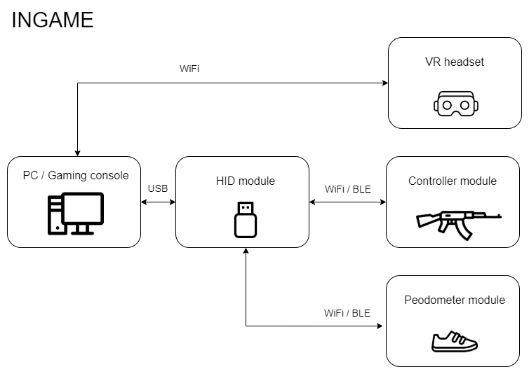
INGAME is a motion emulator with virtual reality features for playing first person shooting/adventure games. Virtual reality (VR) is a simulated experience that can be similar to or completely different from the real world. INGAME has been designed to provide the user with the feeling of being 'IN-the-GAME'. INGAME is modular in nature and consists of the following modules.
The first three modules listed above have been explained in detail later in the document. The VR headset provides split stereo video to the user. The following image shows the functional block diagram of the INGAME system
| Qty | Value | Footprint | References |
|---|---|---|---|
| 4 | MountingHole | MountingHole:MountingHole_2.2mm_M2 | H1, H2, H3, H4 |
| 3 | Conn_01x06 | Board:SolderWire_1x06_P2.54mm | J2, J3, J6 |
| 2 | 10k | Resistor_SMD:R_0805_2012Metric_Pad1.20x1.40mm_HandSolder | R4, R5 |
| 2 | 1k | Resistor_SMD:R_0805_2012Metric_Pad1.20x1.40mm_HandSolder | R2, R3 |
| 2 | LED | LED_SMD:LED_0805_2012Metric_Pad1.15x1.40mm_HandSolder | D1, D2 |
| 1 | 100nF | Capacitor_SMD:C_0805_2012Metric_Pad1.18x1.45mm_HandSolder | C1 |
| 1 | 10K | Resistor_SMD:R_0805_2012Metric_Pad1.20x1.40mm_HandSolder | R1 |
| 1 | 10uF | Capacitor_SMD:C_0805_2012Metric_Pad1.18x1.45mm_HandSolder | CS1 |
| 1 | 22uF | Capacitor_SMD:C_0805_2012Metric_Pad1.18x1.45mm_HandSolder | CS2 |
| 1 | BATTERY | Board:SolderWire_1x02_P2.00mm | J1 |
| 1 | Conn_01x04 | Board:SolderWire_1x04_P2.54mm | J5 |
| 1 | Conn_01x05 | Board:SolderWire_1x05_P2.54mm | J4 |
| 1 | ESP32-WROOM-32 | RF_Module:ESP32-WROOM-32 | U1 |
| 1 | HT7533-1-SOT89 | Package_TO_SOT_SMD:SOT-89-3 | U2 |
| 1 | LSM6DS3 | Package_LGA:LGA-14_3x2.5mm_P0.5mm_LayoutBorder3x4y | U3 |
| 1 | RESET | Button_Switch_SMD:SW_SPST_B3U-1000P | SW1 |
InputBlackBoxOutput/INGAME
Virtual reality controller for playing FPS games

InputBlackBoxOutput/INGAME
Virtual reality controller for playing FPS games


tmjnijssen/OSCD_demo_PCB
Open Science Community Delft demonstration PCB


pms67/Airspeed_SensorBoard
Differential pressure sensor breakout board with STM32 (I2C-to-SPI) interface.

EvanKrall/ipad_touchscreen_driver
A PCB designed to interface with the iPad (A1219) touchscreen


npgo22/mixedsignal
A follow-along of Philip Salmony's Mixed-Signal Hardware Design with KiCad


It measures 45 × 30 mm and has 2 copper layers, 1.6 mm thick.
24 parts, built around the ESP32-WROOM-32, HT7533-1(SOT89-3) and LSM6DS3. The full list of its parts is on this page, with links to each part's symbol and footprint where PCBKit's library has them.
From the InputBlackBoxOutput/INGAME repository on GitHub, at the commit this page was made from: the board is modules/Stick module/board/board.kicad_pcb and its schematic modules/Controller module/board/BMS.kicad_sch. PCBKit opens the board in the browser, with nothing to install.
Its repository publishes it under the MIT licence: you may reuse it on that licence's terms (keep the author's notice, and for a copyleft licence share your changes alike).