
4 layers180.4 × 157.2 mm

 Infecta/837-15330-Pico3
Source files for a fun controller
Slidrr cy8c is an open-source printed circuit board by Infecta, from the Infecta/837-15330-Pico repository on GitHub. It is a 2-layer board of 500 × 136.5 mm with 122 parts on 140 nets, routed with 767 tracks and 212 vias.
It is built around the SN74LV1T34DBVR-TP and SK6812MINI-E. Its parts include 38 capacitors, 37 resistors, 31 diodes, 5 connectors and 4 ICs.


[!WARNING]
This repo is still a work-in-progress state
Some things might be missing until I can finish up on my side.
An attempt at a recreation of the official CHUNITHM Ground Slider for home use.
This project aims to use the same hardware* and firmware of the real ground slider for a more accurate and faithful recreation of CHUNITHM's ground slider input.
*Same PSoCs. LED driver, power management and other things are ignored.
It all started because I couldn't get a thick (3mm) acrylic overlay working on my original simpl-slidrr project simply due to the fact that the MPR121s perform badly on any overlay above 2mm in thickness.
With this project, since we are using the same PSoCs as the official ground slider it gives us the following benefits:
[!WARNING]
Agentic AI usage disclosure
A huge chunk of the code was provided by an AI agent. This only applies to the firmware for the RP2040 Zero.
You may experience weird issues, whacky edge cases that might happen.
The main CY8C22345 communicates to the RP2040 through UART. The firmware will pass those commands transparently unless it's an LED packet in which case, will be parsed by the RP2040 itself to drive the LEDs
To put it in simple terms, the main job of the RP2040 is a Serial to USB adapter*
*If we just gloss over the fact it also does air tower and IO4 emulation
graph LR;
CY(Main CY8C22345)
PICO(RP2040)
LEDS(SK6812MINI-E Array)
Q{IS IT AN LED PACKET}

HOST --> PICO
PICO --> Q
Q --> |NO| CY
Q --> |YES|LED(Parse LED Data) --> LEDS
Very simplified flowchart of what it does.
All SMD components are 0603 unless stated otherwise
| Item | Quantity | Notes |
|---|---|---|
| CY8C22345 | 2 | Link(Taobao). Same chips used as the official ground slider. Depending on where you are, these may be easier or harder to source. Must be an SSOP-28 package to fit on the PCB. If you found a different package you'll have modify the PCB. Get extras just in case things go wrong (bad chip, broken pins etc.) |
| Arduino Pro Micro | 1 | A cheap (and slightly difficult) way to flash the PSoC with the ground slider firmware using arduino_hssp. Make sure it's the 5V model. NOTE: You will need linux to use this with psocdude. If you have another way of programming the PSoC like a MiniProg then go that route. |
| WaveShare RP2040 Zero | 1 | Main brains (UART Passthrough, IO4, LED driver) |
| This SMD tactile switch | 2 | I'm not sure what these are formally called. but I used these for the footprint on the PCB. |
| SN74LV1T34DBVR Logic Level Shifter | 1 | This is for the SK6812MINI-E LED data pins (Needs 5V logic rather than 3.3V logic). You can substitute this with any other level shifter provided it's pin compatible or modify the PCB if you want to use a different one. |
| SK6812MINI-E LEDs | 31 | LEDs. |
| 4x DIP switch | 1 | Temporary but needed during flashing & troubleshooting. Mainly to connect both PSoC I2C lines and connect to the I2C pull-up resistors. |
| JST XH5 Connectors | 2 | Optional. But nice to have to reliably flash PSoCs |
| JST XH6 Connectors | 2 | For connecting air towers |
| 100nf/0.1uF X5R Capacitors | 32 | Decoupling caps for level shifter and LEDs |
| 4.7uF X5R Capacitors | 4 | Decoupling caps for PSoCs |
| 4.7nF X7R Capacitors | 2 | CapSenseTM Modulator cap |
| 560R/560ohm Resistors | 32 | Placed before the touch electrodes. Values are just an estimate and typical range I have tested. |
| 1K Resistor | 1 | Part of a voltage divider to shift down the 5V UART signal to 3.3V going into the RP2040 Zero |
| 2K Resistor | 1 | Part of a voltage divider to shift down the 5V UART signal to 3.3V going into the RP2040 Zero |
| 3K - 4.7K Resistor | 2 | I2C pull-up resistors. Within this range should be fine. |
| 330R/330ohm Resistor | 1 | Needed for the logic level shifter. Followed datasheet. If changing level shifter check datasheet for info. |
| whowechina chu_pico IR airs | 1 pair | IR tower code based around this design. Check chu_pico repo for more info. IMPORTANT: CURRENT LIMITING RESISTORS NEED TO BE CHANGED TO A HIGHER VALUE. CHECK BELOW. |
[!WARNING]
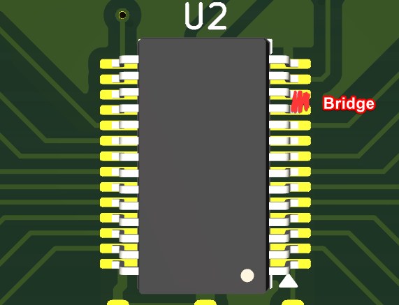
If you have fabricated a PCB before 11th October 2026; Bridge Pin 11 and 12 of U2's pins. I discovered the controller stopped working seemingly out of nowhere due to the floating UART pins on the 2nd PSoC. Huge thanks to @somewhatlurker from the Cons&Stuff discord for helping me troubleshoot this.
The chu_pico airs draw too much power with 0.75ohm resistor (If we were to follow whowe's guide for the airs). Either due to the WaveShare RP2040 zero's 3v3 regulator or general power budget it is too high and there will not be enough power to go around.
[!WARNING]
Using the airs as-is with the 0.75ohm resistors may burn out the 3v3 regulator as it can get very hot.
I suggest using a 50ohm or 100ohm resistor instead. You can almost use down to 10ohms, anything lower doesn't work.
This doc fully assumes you are comfortable with soldering SMD components.
Protip: Use the Interactive Html Bom plugin on KiCAD to easily figure out where all the components go.
We're using JLCPCB for this guide.
You can leave everything on default but I recommend a black solder mask so that the lights look better
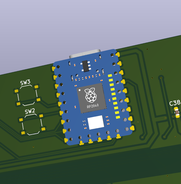
I won't lie, I forgot why I even placed the footprint they way I did. But the RP2040 chip is facing upwards so please keep that in mind.
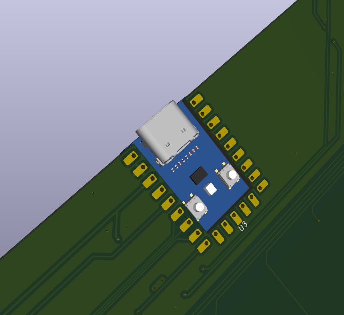
This section will assume you are doing the psocdude + arduino_hssp route.
This also assumes you have sourced your own dump of the offical 837-15330/Ground slider firmware
This section will not guide you on how to flash the arduino or compile psocdude. Use google or ask an LLM for guidance.
Few things are needed to change in the psocdude.conf file in order to get it flashed.
Inside psocdude.conf find the CY8C22345 line. It should look like this.
#------------------------------------------------------------
# CY8C22345
#------------------------------------------------------------

part
  id      = "CY8C22345";
  desc    = "CY8C22345";
  signature   = 0x00 0xD1;
  checksum_setup = CHECKSUM_SETUP_22_24_28_29_TST120_TMG120_TMA120;
  program_block = PROGRAM_BLOCK_21_22_23_24_28_29_TST_TMG_TMA;
  multi_bank = yes;
  memory "signature"
    size = 2;
  ;
;
Change it so it looks like this:
#------------------------------------------------------------
# CY8C22345
#------------------------------------------------------------

part
  id      = "CY8C22345";
  desc    = "CY8C22345";
  signature   = 0x00 0xD0;
  checksum_setup = CHECKSUM_SETUP_22_24_28_29_TST120_TMG120_TMA120;
  program_block = PROGRAM_BLOCK_21_22_23_24_28_29_TST_TMG_TMA;
  multi_bank = yes;
  memory "flash"
    paged     = yes;
    size      = 16384;
    page_size = 64;
    num_pages = 256;
    blocksize = 64;
    readsize  = 64;
  ;
  memory "signature"
    size = 2;
  ;
;
Flash the PSoC with:
psocdude -C psocdude.conf -p CY8C22345 -c arduino -P /dev/ttyACM0 -b 115200 -U flash:w:<DUMPED_FIRMWARE.bin/.hex>:r -FScenario 1
If your output looks like this:
Reading |                     | 0% 0.00spsocdude: ser_recv(): proggrammer is not responding
psocdude: error reading signature data for part "CY8C22345", rc=-1
psocdude: error reading signature data, rc=-1
It could be either one of 2 issues:
Unplug and replug your programmer, then try running the command again.
If that doesn't work check your solder connections.
Scenario 2
If your signature is 0xffff
I haven't figured out why this happens as of writing this. My only solution was switching out the chips with the extras I already had.
There might be more issues that I haven't experienced yet so I can't cover all bases.
TODO: CASE GUIDE HERE
whowechina - Air Code and PCB is heavily referenced and adapted for the firmware from the chu_pico project.
Cons&Stuff Discord Server - For guidance and troubleshooting of my project especially somewhatlurker for their insight of the slider protocol.
| Qty | Value | Footprint | References |
|---|---|---|---|
| 32 | 0.1uF | Capacitor_SMD:C_0603_1608Metric_Pad1.08x0.95mm_HandSolder | C10, C11, C12, C13, C14, C15, C16, C17, C18, C19, C20, C21, C22, C23, C24, C25 +16 |
| 32 | 560R | Resistor_SMD:R_0603_1608Metric_Pad0.98x0.95mm_HandSolder | R10, R11, R12, R13, R14, R15, R16, R17, R18, R19, R20, R21, R22, R23, R24, R25 +16 |
| 31 | SK6812MINI-E | LED_SMD:LED_SK6812MINI-E_3.2x2.8mm_P1.5mm_ReverseMount | D1, D2, D10, D11, D12, D13, D14, D15, D16, D17, D18, D19, D20, D21, D22, D23 +15 |
| 4 | X5R 4.7uF 16V | Capacitor_SMD:C_0603_1608Metric_Pad1.08x0.95mm_HandSolder | C2, C4, C5, C6 |
| 2 | 3.2K | Resistor_SMD:R_0603_1608Metric_Pad0.98x0.95mm_HandSolder | R1, R2 |
| 2 | 4.7nF X7R / 2.2nF X7R | Capacitor_SMD:C_0603_1608Metric_Pad1.08x0.95mm_HandSolder | C1, C3 |
| 2 | JST-XH Series | Connector_JST:JST_XH_S6B-XH-A_1x06_P2.50mm_Horizontal | J4, J5 |
| 2 | SW_Push | Button_Switch_SMD:SW_Push_1P1T_XKB_TS-1187A | SW2, SW3 |
| 2 | ~ | Package_SO:SSOP-28_5.3x10.2mm_P0.65mm | U1, U2 |
| 1 | 1K | Resistor_SMD:R_0603_1608Metric_Pad0.98x0.95mm_HandSolder | R35 |
| 1 | 2K | Resistor_SMD:R_0603_1608Metric_Pad0.98x0.95mm_HandSolder | R36 |
| 1 | 330R | Resistor_SMD:R_0603_1608Metric_Pad0.98x0.95mm_HandSolder | R37 |
| 1 | Conn_01x32_Socket | slidrr-touchslider:slidrr-touchslider | J3 |
| 1 | ISSP U1 | Connector_JST:JST_XH_B5B-XH-A_1x05_P2.50mm_Vertical | J1 |
| 1 | ISSP U2 | Connector_JST:JST_XH_B5B-XH-A_1x05_P2.50mm_Vertical | J2 |
| 1 | SN74LV1T34DBVR | Package_TO_SOT_SMD:SOT-23-5 | U5 |
| 1 | SW1 | Jumper:SolderJumper-2_P1.3mm_Open_TrianglePad1.0x1.5mm | JP1 |
| 1 | SW2 | Jumper:SolderJumper-2_P1.3mm_Open_TrianglePad1.0x1.5mm | JP2 |
| 1 | SW3 | Jumper:SolderJumper-2_P1.3mm_Open_TrianglePad1.0x1.5mm | JP3 |
| 1 | SW4 | Jumper:SolderJumper-2_P1.3mm_Open_TrianglePad1.0x1.5mm | JP4 |
| 1 | SW_DIP_x04 | Button_Switch_SMD:SW_DIP_SPSTx04_Slide_9.78x12.34mm_W8.61mm_P2.54mm | SW1 |
| 1 | ~ | RP2040-Zero:RP2040-Zero | U3 |


brenocq/bldc-motor
High-precision BLDC motor and controller development from scratch (in progress...)

YuuichiAkagawa/USBMIDItoSyncConverter
Converts USB MIDI clock messages to sync signals


3amon/leaderless-light-mesh
Wearable LED rings that keep a shared clock with no leader: Zephyr/OpenThread firmware, signed OTA, carrier PCB, simulators and hardware evidence


azais-corentin/espion
Multi-camera IR marker tracking: ESP32-P4/C5 firmware, Rust host, KiCad hardware
It measures 500 × 136.5 mm and has 2 copper layers, 1.6 mm thick.
122 parts, built around the SN74LV1T34DBVR-TP and SK6812MINI-E. The full list of its parts is on this page, with links to each part's symbol and footprint where PCBKit's library has them.
From the Infecta/837-15330-Pico repository on GitHub, at the commit this page was made from: the board is KiCAD-project-files/slidrr-cy8c.kicad_pcb and its schematic KiCAD-project-files/slidrr-cy8c.kicad_sch. PCBKit opens the board in the browser, with nothing to install.
Its repository states no licence, so its author keeps all rights: ask Infecta before reusing the design.