20 layers228.6 × 304.8 mm

 IDiAL-IMSL/Edurob-PCB1
PCB-Files for Edurob
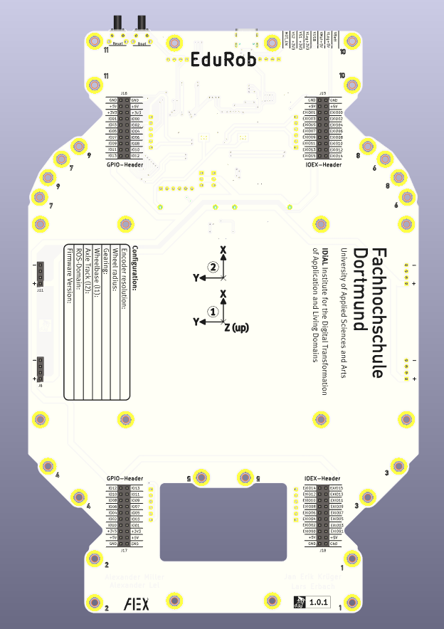
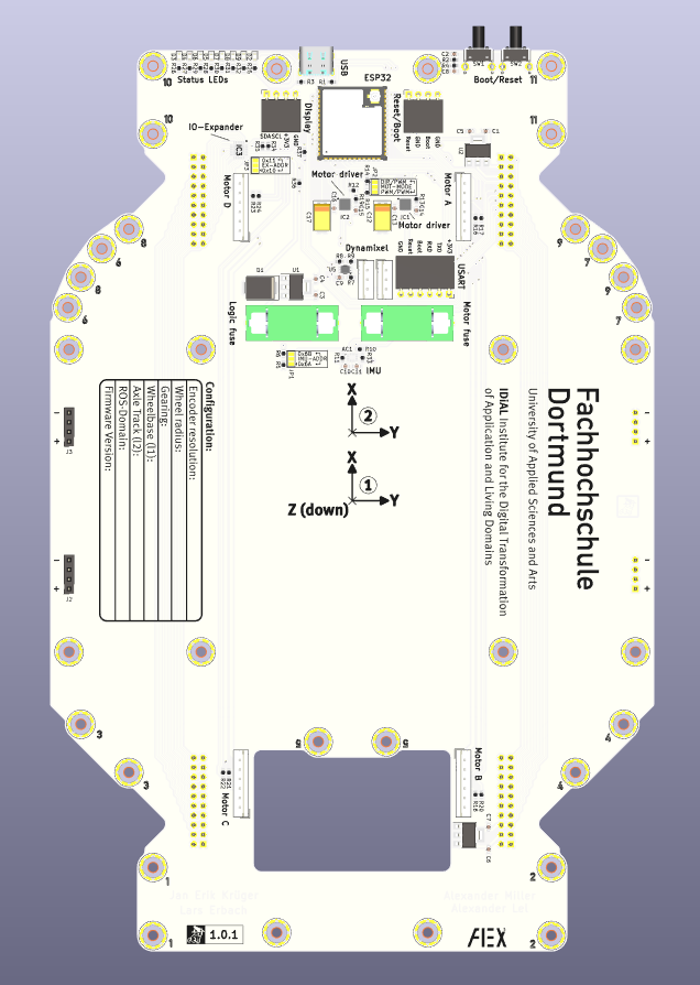
Edurob is an open-source printed circuit board by IDiAL-IMSL, from the IDiAL-IMSL/Edurob-PCB repository on GitHub, published under the BSD-3-Clause licence. It is a 2-layer board of 160 × 238.5 mm with 139 parts on 110 nets, routed with 1,948 tracks and 137 vias.
It is built around the ESP32-S3-WROOM-1-N8, TC78H660FTG,EL and PI4IOE5V6416ZDEX, with the SMTSO-M3-2ET, 0PTF0078P and 12402012E212A among its other parts. Its parts include 37 resistors, 18 connectors, 17 capacitors, 9 diodes and 8 ICs. It belongs with the ESP32 boards of this library.


PCB-Files for Edurob
| Qty | Value | Footprint | References |
|---|---|---|---|
| 34 | SMTSO-M3-2ET | Footprints:SMTSO-M3-2ET | H1, H2, H10, H11, H12, H15, H16, H17, H18, H19, H20, H21, H22, H23, H24, H29 +18 |
| 25 | 10K | Resistor_SMD:R_0603_1608Metric | R2, R10, R11, R12, R14, R15, R16, R17, R18, R20, R21, R22, R23, R24, R33, R34 +9 |
| 8 | LED | LED_SMD:LED_0603_1608Metric | D2, D3, D4, D5, D6, D7, D8, D9 |
| 7 | 100nF | Capacitor_SMD:C_0603_1608Metric | C9, C10, C11, C13, C14, C15, C16 |
| 4 | 130R | Resistor_SMD:R_0603_1608Metric | R25, R30, R31, R32 |
| 4 | 300R | Resistor_SMD:R_0603_1608Metric | R26, R27, R28, R29 |
| 4 | Conn_01x04_Pin | Connector_PinSocket_2.54mm:PinSocket_1x04_P2.54mm_Vertical | J2, J3, J6, J11 |
| 4 | Conn_01x06_Pin | Connector_JST:JST_EH_B6B-EH-A_1x06_P2.50mm_Vertical | J8, J12, J13, J14 |
| 4 | Conn_01x20_Pin | Connector_PinSocket_2.54mm:PinSocket_2x10_P2.54mm_Vertical | J15, J16, J17, J18 |
| 3 | 10uF | Capacitor_SMD:C_0603_1608Metric | C1, C3, C6 |
| 3 | 22uF | Capacitor_SMD:C_0603_1608Metric | C4, C5, C7 |
| 3 | AZ1117-3.3 | Package_TO_SOT_SMD:SOT-223-3_TabPin2 | U1, U2, U3 |
| 3 | SolderJumper_3_Open | Jumper:SolderJumper-3_P1.3mm_Open_Pad1.0x1.5mm | JP1, JP2, JP3 |
| 2 | 0PTF0078P | Footprints:0PTF0078P | F1, F2 |
| 2 | 1uF | Capacitor_SMD:C_0603_1608Metric | C2, C8 |
| 2 | 47K | Resistor_SMD:R_0603_1608Metric | R13, R19 |
| 2 | 47uF | Capacitor_Tantalum_SMD:CP_EIA-7343-31_Kemet-D | C12, C17 |
| 2 | 5k1 | Resistor_SMD:R_0603_1608Metric | R1, R3 |
| 2 | Alex² | Footprints:Alex2 | LOGO3, LOGO8 |
| 2 | Conn_01x03_Male | Connector_JST:JST_EH_B3B-EH-A_1x03_P2.50mm_Vertical | J9, J10 |
| 2 | FH Dortmund | Footprints:FHDO | LOGO4, LOGO9 |
| 2 | SW_Push | Button_Switch_THT:SW_Tactile_SPST_Angled_PTS645Vx83-2LFS | SW1, SW2 |
| 2 | TC78H660FTG,EL | Footprints:QFN50P300X300X90-17N | IC1, IC2 |
| 2 | Wizcat | Footprints:Logo_Cat_Copper_5x5 | LOGO2, LOGO7 |
| 2 | Wizcat Label | Footprints:Logo_Cat_15x5_1 | LOGO1, LOGO6 |
| 1 | 12402012E212A | Footprints:AMPHENOL_12402012E212A | J4 |
| 1 | B320 | Diode_SMD:D_SMC | D1 |
| 1 | Conn_01x04_Pin | Connector_PinSocket_2.54mm:PinSocket_1x04_P2.54mm_Horizontal | J5 |
| 1 | Conn_01x06_Pin | Connector_PinSocket_2.54mm:PinSocket_1x06_P2.54mm_Horizontal | J7 |
| 1 | DCU8 | Footprints:74LVC2G241DCUTG4 | U5 |
| 1 | ESP32-S3-WROOM-1 | Footprints:ESP32-S3-WROOM-1U | U4 |
| 1 | LSM6DSOXTR | Footprints:LGA-14_1 | AC1 |
| 1 | OLED | Connector_PinSocket_2.54mm:PinSocket_1x04_P2.54mm_Horizontal | J1 |
| 1 | PI4IOE5V6416ZDEX | Footprints:QFN50P400X400X90-25N | IC3 |


Caroma97/WT32-ETH01_PWM_Fan_Controller
esphome compartible dual fan controller

Connaxio/production-controller-makroshield
The PCM has a mikroBUS socket that works with Espoir, our Power over Ethernet devboard, to provide remote control, as well as advanced functionalities through node-red and Home Assistant.


EdSmithe/meniscus-controller
Closed-loop meniscus pressure controller for inkjet printing: custom KiCad PCB, Arduino control firmware, Python GUI

Immortals-Robotics/MainBoard
Immortals main electronics for the Robocup Soccer Small-Size League

NA-varez/OMNIXIE
Nixie driver board to enable easy inclusion of a Nixie tube into projects. One common driver board to support a wide range of Nixie Indicator Tubes
It measures 160 × 238.5 mm and has 2 copper layers, 1.6 mm thick.
139 parts, built around the ESP32-S3-WROOM-1-N8, TC78H660FTG,EL, PI4IOE5V6416ZDEX and SMTSO-M3-2ET. The full list of its parts is on this page, with links to each part's symbol and footprint where PCBKit's library has them.
From the IDiAL-IMSL/Edurob-PCB repository on GitHub, at the commit this page was made from: the board is Edurob/Edurob.kicad_pcb and its schematic Edurob/Connectors.kicad_sch. PCBKit opens the board in the browser, with nothing to install.
Its repository publishes it under the BSD-3-Clause licence: you may reuse it on that licence's terms (keep the author's notice, and for a copyleft licence share your changes alike).