2 layers204.5 × 113 mm

 HexFud/Bench-power-supply
I designed a simple and cost effective bench power supply for everyone. To simplify the assmebly process i designed in kicad a small pcb where you connect external components
Bench power supply is an open-source printed circuit board by HexFud, from the HexFud/Bench-power-supply repository on GitHub. It is a 2-layer board of 74.4 × 73.9 mm with 31 parts on 44 nets, routed with 269 tracks and 48 vias.
It is built around the LM2596S-12, AMS1117-3.3 and SMBJ36A. Its parts include 10 connectors, 5 capacitors, 3 diodes, 2 resistors and 2 ICs. It belongs with the power boards and the ESP32 and AVR (ATmega, ATtiny) boards of this library.


I designed a simple and cost effective bench power supply for everyone. To simplify the assmebly process i designed in kicad a small pcb where you connect external components
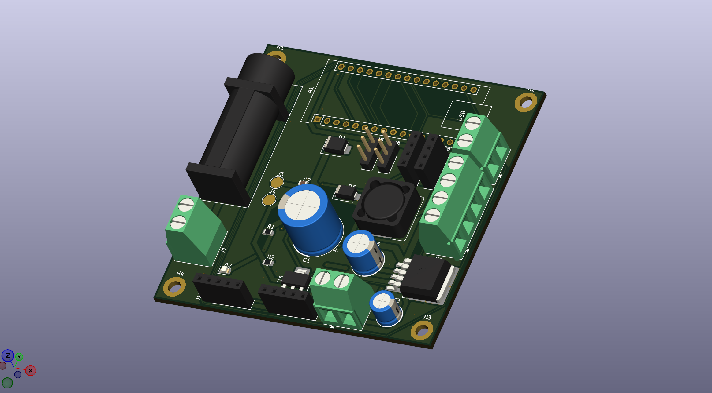
Firmware/bench_psu.inoJ8 on this PCB is purposely designed with only 3 pins for the thin wires).| Qty | Value | Footprint | References |
|---|---|---|---|
| 4 | MountingHole_Pad | MountingHole:MountingHole_3.2mm_M3_DIN965_Pad | H1, H2, H3, H4 |
| 2 | 10k | Resistor_SMD:R_0805_2012Metric | R1, R2 |
| 2 | Conn_01x01_Socket | TestPoint:TestPoint_Pad_D3.0mm | J3, J4 |
| 2 | Conn_01x03_Socket | Connector_PinHeader_2.54mm:PinHeader_1x03_P2.54mm_Vertical | J5, J6 |
| 2 | Conn_01x04_Socket | Connector_PinSocket_2.54mm:PinSocket_1x04_P2.54mm_Vertical | J2, J8 |
| 2 | Conn_01x05_Socket | Connector_PinSocket_2.54mm:PinSocket_1x05_P2.54mm_Vertical | J9, J10 |
| 2 | SW_SPST | TerminalBlock_Phoenix:TerminalBlock_Phoenix_MKDS-1,5-2-5.08_1x02_P5.08mm_Horizontal | SW1, SW2 |
| 1 | 1000uF 50V | Capacitor_THT:CP_Radial_D12.5mm_P5.00mm | C1 |
| 1 | 100nF 50V | Capacitor_SMD:C_0805_2012Metric | C2 |
| 1 | 100uF 30V | Capacitor_THT:CP_Radial_D6.3mm_P2.50mm | C3 |
| 1 | 220uF 50V | Capacitor_THT:CP_Radial_D8.0mm_P3.50mm | C5 |
| 1 | 22uF 10V | Capacitor_SMD:C_0805_2012Metric | C4 |
| 1 | 24V | TerminalBlock_Phoenix:TerminalBlock_Phoenix_MKDS-1,5-2-5.08_1x02_P5.08mm_Horizontal | J1 |
| 1 | 6,3A | Fuse:Fuseholder_Cylinder-5x20mm_Bulgin_FX0457_Horizontal_Closed | F1 |
| 1 | AMS1117-3.3 | Package_TO_SOT_SMD:SOT-223-3_TabPin2 | U3 |
| 1 | Arduino_Nano_ESP32 | Module:Arduino_Nano | A1 |
| 1 | Conn_01x04_Socket | TerminalBlock_Phoenix:TerminalBlock_Phoenix_MKDS-1,5-4-5.08_1x04_P5.08mm_Horizontal | J7 |
| 1 | D_Schottky | Diode_SMD:D_SMA | D3 |
| 1 | L | Inductor_SMD:L_Bourns_SRR1260 | L1 |
| 1 | LED | LED_SMD:LED_0805_2012Metric | D2 |
| 1 | LM2596S-12 | Package_TO_SOT_SMD:TO-263-5_TabPin3 | U5 |
| 1 | SMBJ36A | Diode_SMD:D_SMB | D1 |

HexFud/HexArm
I created this 6 axis robotic arm entirely from scratch starting from the PCB to the 3D modelling and designing.

alcaaron/esi_project
ENGINYERIA DE SISTEMES: PROJECTE DE CURS Fet per - Aaron Alcalá - Albert Bombí - Marcos García


mrkubag/SMT_stopper
Projekt sterownika automatycznie regulowanego stopera wbudowanego w transporter PCB.

TCC-Sumo-Telemetria/Eletronica_Sumo_Telemetria
Projetos eletrônicos relacionados ao trabalho de conclusão de curso "SISTEMA DE TELEMETRIA PARA A AVALIAÇÃO DE DESEMPENHO DE UM ROBÔ DE MEGA SUMÔ AUTÔNOMO".

PSU-Ext-Org/psu-ext-hardware
A repository to store PSU-EXT hardware design assets, schematics, circuit diagrams, CAD files and manufacturing data.

It measures 74.4 × 73.9 mm and has 2 copper layers, 1.6 mm thick.
31 parts, built around the LM2596S-12, AMS1117-3.3 and SMBJ36A. The full list of its parts is on this page, with links to each part's symbol and footprint where PCBKit's library has them.
From the HexFud/Bench-power-supply repository on GitHub, at the commit this page was made from: the board is PCB/Bench_Power_supply.kicad_pcb and its schematic PCB/Bench_Power_supply.kicad_sch. PCBKit opens the board in the browser, with nothing to install.
Its repository states no licence, so its author keeps all rights: ask HexFud before reusing the design.