
4 layers234 × 84 mm
Main panel
google/mozc-devices
Circuit diagrams and firmware source code for Gboard DIY keyboards
234 parts3kApache-2.0

 Hasnat4763/Commiepad-V21
A fully custom designed macro pad. It is a sequel to my 1st macropad design Commiepad. The 1st one was not working fully as I had made some mistakes in the PCB by not using a matrix and combining OLED SDA with neopixel…
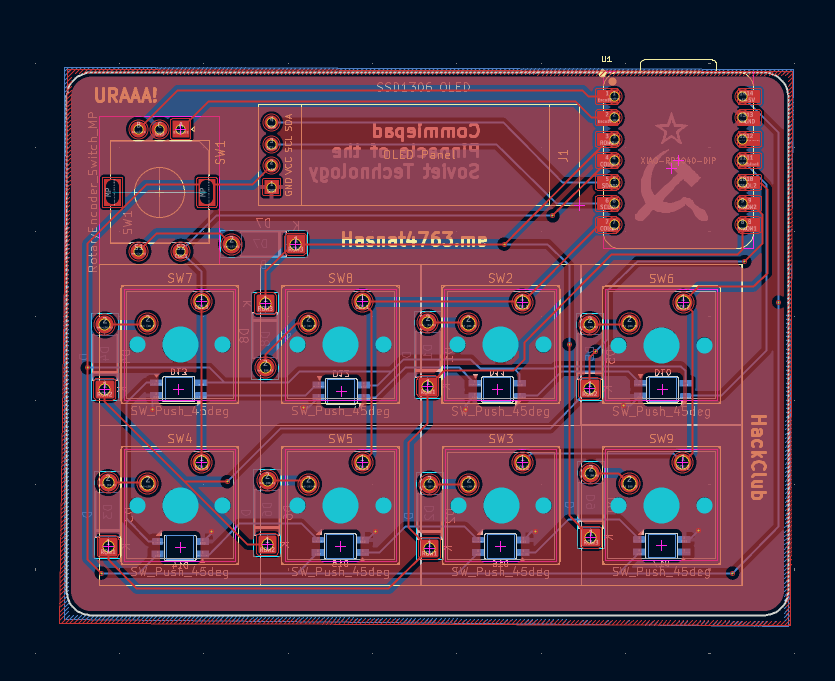
Commiepad V2 is an open-source printed circuit board by Hasnat4763, from the Hasnat4763/Commiepad-V2 repository on GitHub, published under the MIT licence. It is a 2-layer board of 85.6 × 64.4 mm with 29 parts on 32 nets, routed with 211 tracks and 19 vias.
It is built around the SK6812MINI-E. Its parts include 17 diodes, 9 switches, 1 IC and 1 connector. It belongs with the lEDs and displays boards and the RP2040 boards of this library.
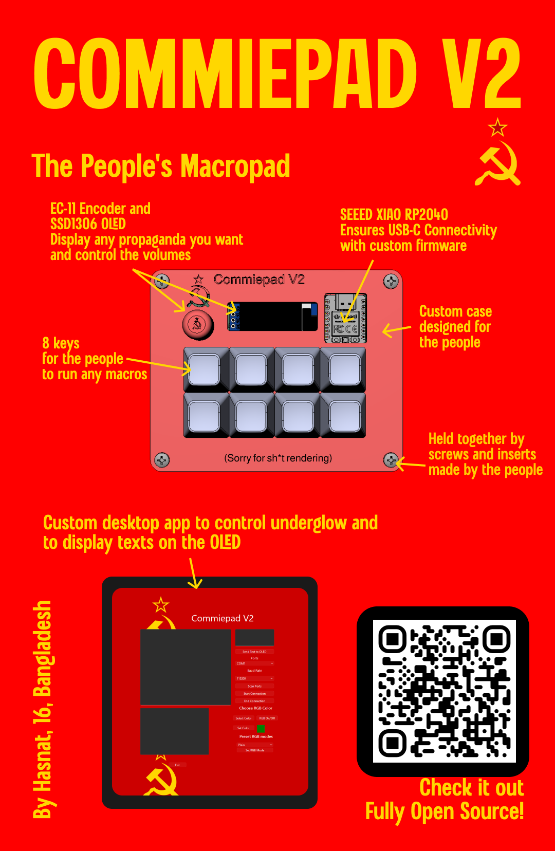
A fully custom designed macro pad. It is a sequel to my 1st macropad design Commiepad. The 1st one was not working fully as I had made some mistakes in the PCB by not using a matrix and combining OLED SDA with neopixel data line. So I fixed that mistake in this one. It can be used for running macros which can help people like programmers and designers to run commands they need to run a lot just by clicking one key instead of multiple.
As my 1st hackpad design didn't work, and I had some free time, I thought of designing a new hackpad.
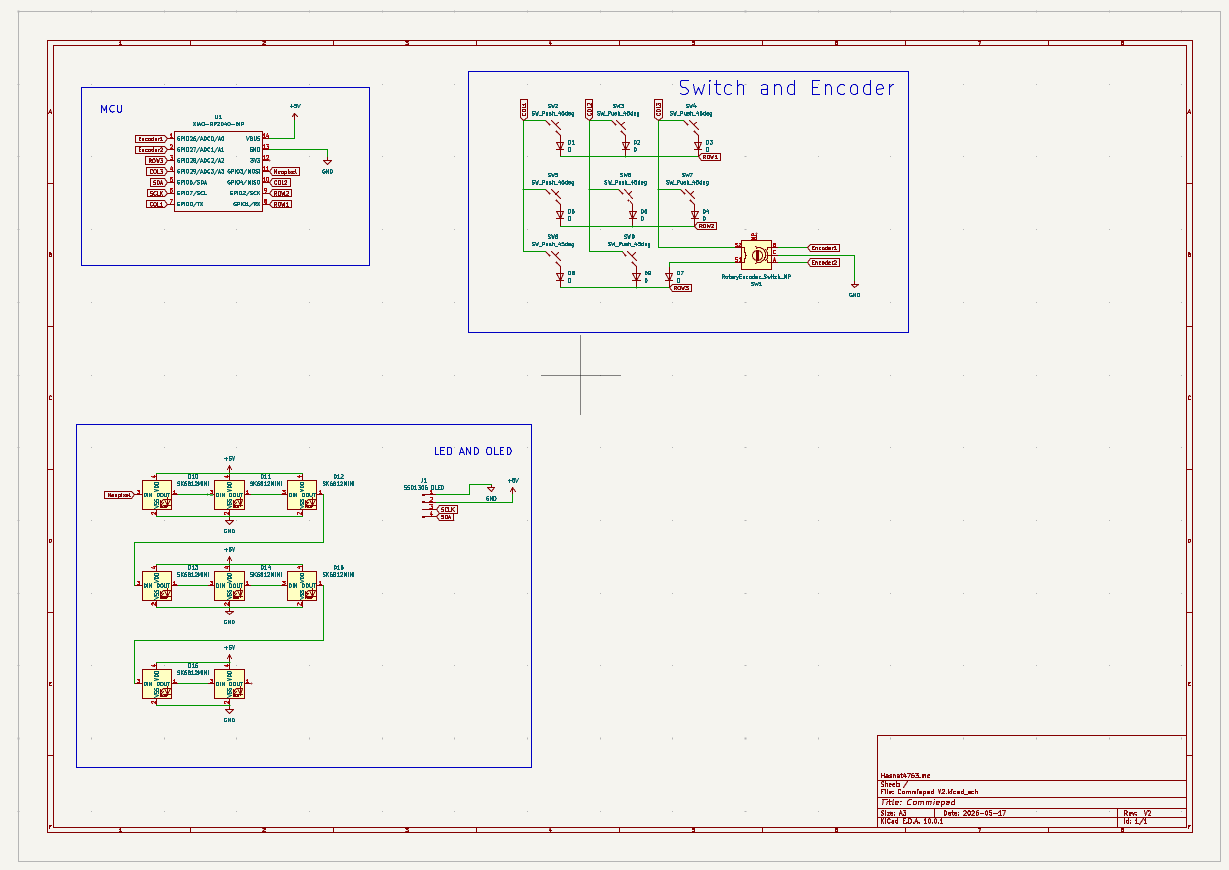
Schematic
PCB
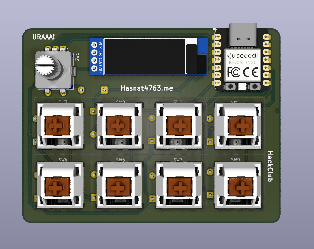
PCB Rendered
Full Board Assembled
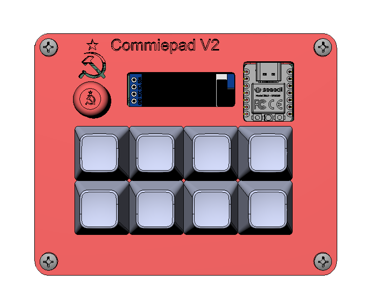
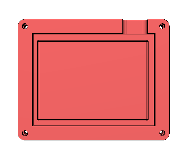
Bottom Part
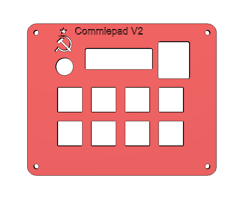
Top Cover
| Item | Quantity | Price | Link |
|---|---|---|---|
| SEEED XIAO RP2040 (THT) | 1 | $$7.25 | Link |
| Outemu Silent Peach V3 Switch | 10 | $6.09 | Link |
| SK6812-MINI-E (RGB LEDs) | 20 | $5.26 | Link |
| 1N4148 Diode | 100 | $1.20 | Link |
| SSD1306 OLED Display | 1 | $5.15 | Link |
| YMDK Blank DSA 1u Keycap | 10 | $6.43 | Link |
| EC 11 Encoder with Push Button Half Handle 20MM Shaft | 5 | $6.31 | Link |
| M3 Heat Set Inserts | 30 | $6.13 | Link |
| M3 Fasteners | 50 | $6.28 | Link |
| Top Case | 1 | Printing Legion | |
| Bottom Case | 1 | Printing Legion | |
| PCB | 5 | $11.02 | JLCPCB |
To fabricate the PCB, use any PCB fabricators you can find for cheap, for most people it's JLCPCB. But then you also have to check the shipping cost and customs of your country. For the parts, aliexpress works. But then you can also get them from your local suppliers too.
First, follow the KMK starter guide to flash KMK on your microcontroller, My repository already has the KMK files necessary with all the extra libraries for the SSD1306 OLED, so you can follow the KMK starter guide but remember to copy the files from this repository instead of the KMK one. Remember to copy the serialcommand.py else you won't be able to use the desktop app to control the RGB underglow. You can change the keys you want the macro pad to press on the main.py, as I have just put some placeholder keys like A, B, C, D etc. for now. You may even make layers so one key can be used to trigger multiple keys!
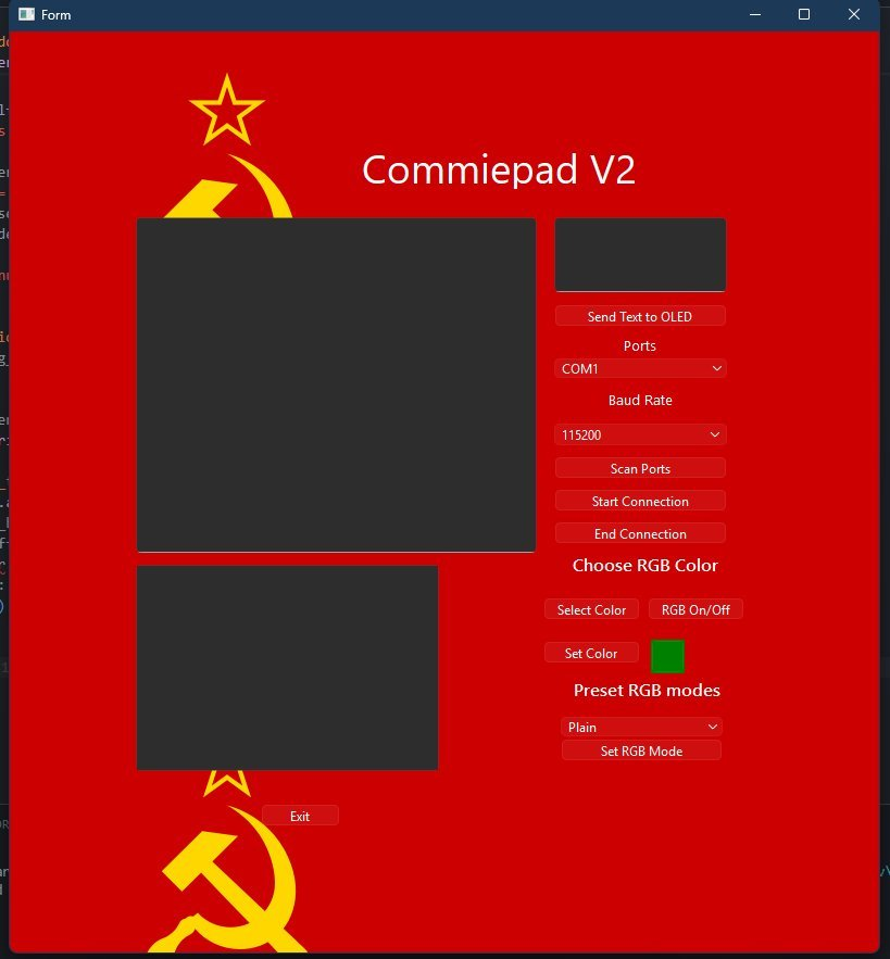
the desktop app looks like this
I have included a build for windows here
To build for Mac/Linux:
# 1. Create virtual environment
python3 -m venv commiepad_env
source commiepad_env/bin/activate

# 2. Install dependencies
pip install -r requirements.txt

# 3. Build executable
pyinstaller --onefile --windowed --add-data "main.ui:." --add-data "bg.png:." --hidden-import=PyQt6.QtCore --hidden-import=PyQt6.QtGui --hidden-import=PyQt6.QtWidgets --hidden-import=PyQt6.uic --name CommiepadV2 main.py
After launching the app, select the COM port your Macropad is connected to, and select the baud rate (Most popular option is 115200), after that click the button called "Start Connection". After successful connection, the debug area will show a message about it. Then you can start controlling the RGB and also put text on the OLED from it.
Features of this app:
I may add some more features to it later. For now these should work (They haven't been tested yet).
| Qty | Value | Footprint | References |
|---|---|---|---|
| 9 | D | Diode_THT:D_DO-41_SOD81_P7.62mm_Horizontal | D1, D2, D3, D4, D5, D6, D7, D8, D9 |
| 8 | SK6812MINI | FSM8JH:SK6812-MINI-E | D10, D11, D12, D13, D14, D15, D16, D17 |
| 8 | SW_Push_45deg | 1N4148:SW_Cherry_MX_1.00u_PCB | SW2, SW3, SW4, SW5, SW6, SW7, SW8, SW9 |
| 1 | LOGO | LOGO | G*** |
| 1 | RotaryEncoder_Switch_MP | 1N4148:RotaryEncoder_Alps_EC11E-Switch_Vertical_H20mm | SW1 |
| 1 | SSD1306 OLED | Seeed Studio XIAO Series Library:SSD1306-0.91-OLED-4pin-128x32 | J1 |
| 1 | XIAO-RP2040-DIP | Seeed Studio XIAO Series Library:XIAO-RP2040-DIP | U1 |
google/mozc-devices
Circuit diagrams and firmware source code for Gboard DIY keyboards

Bastardkb/Dilemma
The Dilemma is a vertical stagger low-profile keyboard with mods.

Pwnsat/FlatSat
Flatsat v1.0 is a hardware based platform for aerospace cybersecurity research

adamws/kicad-kbplacer
KiCad plugin for automatic keyboard's key placement and routing

imchipwood/dumbpad
Simple 4x4 numpad with rotary encoder. Powered by QMK via ATmega32u4 Pro Micro

makerforgetech/modular-biped
An open source framework for creating a bipedal modular companion robot.


It measures 85.6 × 64.4 mm and has 2 copper layers, 1.6 mm thick.
29 parts, built around the SK6812MINI-E. The full list of its parts is on this page, with links to each part's symbol and footprint where PCBKit's library has them.
From the Hasnat4763/Commiepad-V2 repository on GitHub, at the commit this page was made from: the board is PCB/Commiepad V2.kicad_pcb and its schematic PCB/Commiepad V2.kicad_sch. PCBKit opens the board in the browser, with nothing to install.
Its repository publishes it under the MIT licence: you may reuse it on that licence's terms (keep the author's notice, and for a copyleft licence share your changes alike).