
2 layers90.2 × 49.6 mm
Esp32
Hackuarium/esp-32wroom
Start by installing the ESP32 board in Arduino IDE https://randomnerdtutorials.com/installing-the-esp32-board-in-arduino-ide-mac-and-linux-instructions/ (Mac/Linux)…
72 parts

Start by installing the ESP32 board in Arduino IDE https://randomnerdtutorials.com/installing-the-esp32-board-in-arduino-ide-mac-and-linux-instructions/ (Mac/Linux)…
Esp32 is an open-source printed circuit board by Hackuarium, from the Hackuarium/esp-32wroom repository on GitHub. It is a 2-layer board of 85 × 75 mm with 74 parts on 75 nets, routed with 597 tracks and 62 vias.
It is built around the ESP32-WROOM-32U, ACT4088US-T and DS18B20U, with the SI7020-A20-GM, TCS34001FN and AP7365-33YG among its other parts. Its parts include 18 connectors, 15 resistors, 12 capacitors, 8 ICs and 7 diodes. It belongs with the ESP32 boards of this library.


| # | Name | A | SPI | HS | I2C | Touch | Used | RTC |
|---|---|---|---|---|---|---|---|---|
| 1 | GND | |||||||
| 2 | 3V3 | |||||||
| 3 | EN | |||||||
| 4 | SENSOR_VP/IO36 | A0 | RTC_GPIO0 | |||||
| 5 | SENSOR_VN/IO39 | A3 | Charging | RTC_GPIO3 | ||||
| 6 | IO34 | A6 | OneWire1 | RTC_GPIO4 | ||||
| 7 | IO35 | A7 | OneWire2 | RTC_GPIO5 | ||||
| 8 | IO32 | A4 | T9 | Ext3 | RTC_GPIO9 | |||
| 9 | IO33 | A5 | T8 | Ext4 | RTC_GPIO8 | |||
| 10 | IO25 | A18 * | Ext1 | RTC_GPIO6 | ||||
| 11 | IO26 | A19 * | Ext2 | RTC_GPIO7 | ||||
| 12 | IO27 | A17 * | T7 | ADC battery | RTC_GPIO17 | |||
| 13 | IO14 | A16 * | HSPICLK | HS2_CLK | T6 | Blue | RTC_GPIO16 | |
| 14 | IO12 | A15 * | HSPIQ | HS2_DATA2 | T5 | Red | RTC_GPIO15 | |
| 15 | GND | |||||||
| 16 | IO13 | A14 * | HSPID | HS2_DATA3 | T4 | Green | RTC_GPIO14 | |
| 17 | SHD/SD2 | SPIHD | HS1 | |||||
| 18 | SWP/SD3 | SPIWP | ||||||
| 19 | SCS/CMD | SPICS0 | ||||||
| 20 | SCK/CLK | SPICLK | ||||||
| 21 | SDO/SD0 | SPIQ | ||||||
| 22 | SDI/SD1 | SPID | ||||||
| 23 | IO15 | A13 * | HSPICS0 | T3 | White | RTC_GPIO13 | ||
| 24 | IO2 | A12 * | HSPIWP | T2 | RESERVED | RTC_GPIO12 | ||
| 25 | IO0 | A11 * | T1 | Prog | RTC_GPIO11 | |||
| 26 | IO4 | A10 * | HSPIHD | HS2_DATA1 | T0 | OneWire1 | RTC_GPIO10 | |
| 27 | IO16 | HS1_DATA4 | ||||||
| 28 | IO17 | HS1_DATA5 | ||||||
| 29 | IO5 | VSPICS0 | HS1_DATA6 | |||||
| 30 | IO18 | VSPICLK | HS1_DATA7 | Blink LED | ||||
| 31 | IO19 | VSPIQ | ||||||
| 32 | NC | |||||||
| 33 | IO21 | VSPIHD | SDA | SDA | ||||
| 34 | RXD0 | RX | ||||||
| 35 | TXD0 | TX | ||||||
| 36 | IO22 | VSPIWP | SCL | SCL | ||||
| 37 | IO23 | VSPID | HS1_STROBE | |||||
| 38 | GND |
*: not usable with WIFI
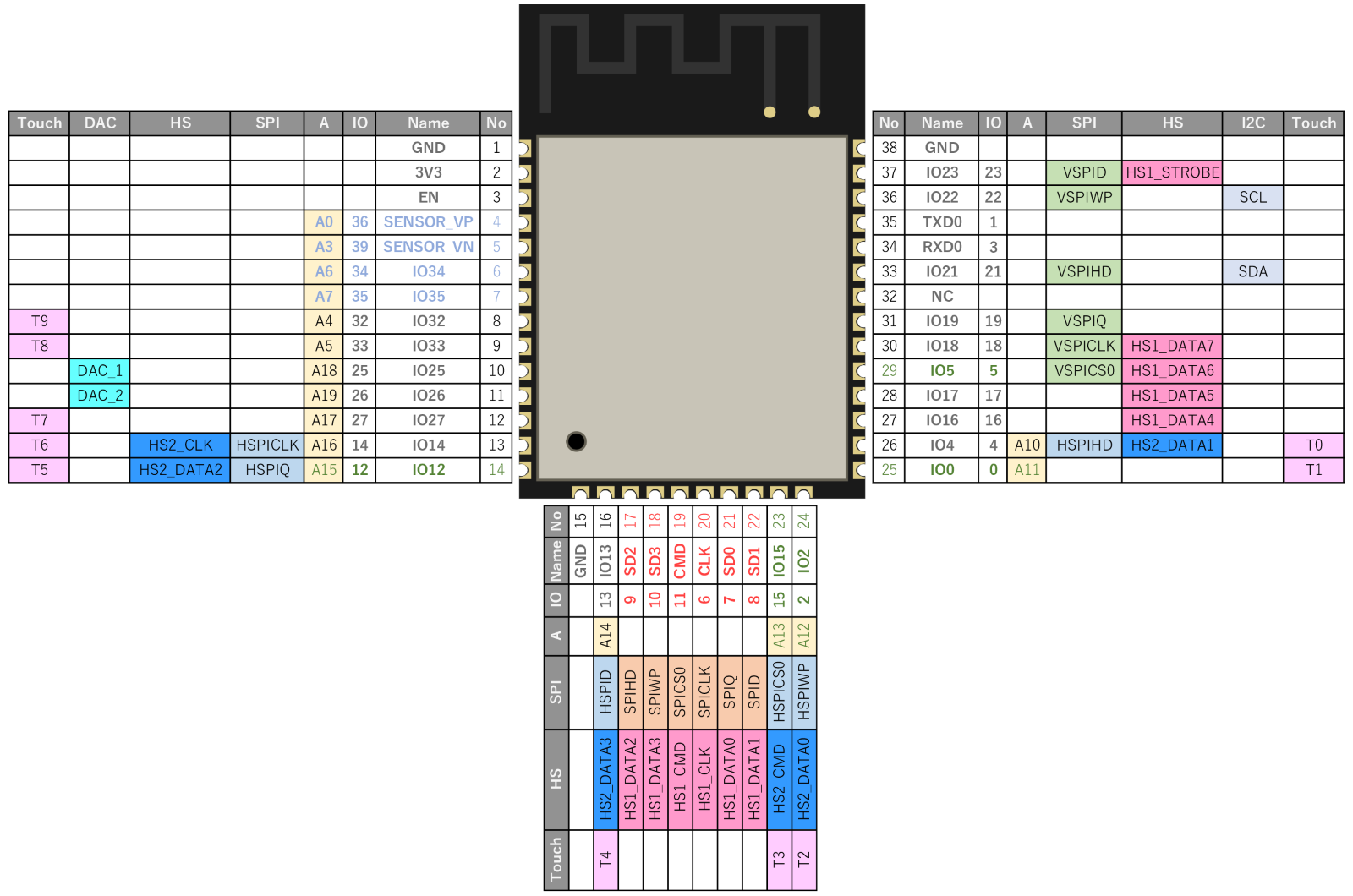
https://www.espressif.com/sites/default/files/documentation/esp32-wroom-32_datasheet_en.pdf
https://www.espressif.com/sites/default/files/documentation/esp32_hardware_design_guidelines_en.pdf
https://www.instructables.com/id/DIY-ESP32-Development-Board-ESPer/
Start by installing the ESP32 board in Arduino IDE https://randomnerdtutorials.com/installing-the-esp32-board-in-arduino-ide-mac-and-linux-instructions/ (Mac/Linux) https://randomnerdtutorials.com/installing-the-esp32-board-in-arduino-ide-windows-instructions/ (Windows)
Getting started with ESP32 (including blink example) https://randomnerdtutorials.com/getting-started-with-esp32/
Some debug information https://github.com/espressif/esptool/wiki/ESP32-Boot-Mode-Selection
In Arduino IDE, select "ESP32 Wrover module" (>tools>boards), connect the UART programmer to the board (make sure it is in the right orientation), select the corresponding port (>tools>port). Write a simple sketch (for example blink using pin18 for the red light), and upload it to the board, after seeing the "Connecting..." message in the lower windows of Arduino IDE, press both buttons (PROG and RESET), release the "RESET" button first and then release the "BOOT" button, the upload should start. After this, press reset so that the latest code runs on the board (you should see the red light blinking).
To avoid worrying about pressing the button, connect 10 uF electrolytic capacitor between the EN pin and GND (may work or not depending on boards...) (https://randomnerdtutorials.com/solved-failed-to-connect-to-esp32-timed-out-waiting-for-packet-header/)
Many ESP32 tutorials/projects are available at Random Nerd Tutorials (web-based, sensor-based, data logging, deep sleep...): https://randomnerdtutorials.com/projects-esp32/
Schema for a dev kit: https://dl.espressif.com/dl/schematics/esp32_devkitc_v4-sch.pdf
Ultra low power tips for ESP32: http://iot-bits.com/ultra-low-power-design-esp32-10-tips/
| Qty | Value | Footprint | References |
|---|---|---|---|
| 6 | 10k | Resistor_SMD:R_0805_2012Metric_Pad1.15x1.40mm_HandSolder | R2, R5, R8, R9, R11, R16 |
| 5 | 10uF | Capacitor_SMD:C_0805_2012Metric_Pad1.15x1.40mm_HandSolder | C2, C3, C4, C5, C6 |
| 4 | BSP75 | Package_TO_SOT_SMD:SOT-223 | Q1, Q2, Q3, Q4 |
| 4 | hole | MountingHole:MountingHole_3.2mm_M3 | J5, J6, J7, J8 |
| 3 | 4.7k | Resistor_SMD:R_0805_2012Metric_Pad1.15x1.40mm_HandSolder | R1, R3, R17 |
| 3 | D_Schottky | Diode_SMD:D_SOD-123 | D1, D3, D5 |
| 2 | 100nF | Capacitor_SMD:C_0805_2012Metric_Pad1.15x1.40mm_HandSolder | C1, C7 |
| 2 | C | Capacitor_SMD:C_0805_2012Metric_Pad1.15x1.40mm_HandSolder | C8, C9 |
| 2 | LED | LED_SMD:LED_0805_2012Metric_Pad1.15x1.40mm_HandSolder | D2, D4 |
| 2 | OneWire | TestPoint:TestPoint_2Pads_Pitch2.54mm_Drill0.8mm | TP1, TP6 |
| 2 | Onewire | Connector_Audio:Jack_3.5mm_Ledino_KB3SPRS_Horizontal | J3, J4 |
| 2 | RJ12-I2C | Connector_RJ:RJ12_Amphenol_54601 | J16, J17 |
| 1 | +12V | Connector_Wire:SolderWirePad_1x01_SMD_5x10mm | J2 |
| 1 | 100k | Resistor_SMD:R_0805_2012Metric_Pad1.15x1.40mm_HandSolder | R6 |
| 1 | 10µF | Capacitor_SMD:C_0805_2012Metric_Pad1.15x1.40mm_HandSolder | C11 |
| 1 | 1M | Resistor_SMD:R_0805_2012Metric_Pad1.15x1.40mm_HandSolder | R7 |
| 1 | 1k | Resistor_SMD:R_0805_2012Metric_Pad1.15x1.40mm_HandSolder | R4 |
| 1 | 22nF | Capacitor_SMD:C_0805_2012Metric_Pad1.15x1.40mm_HandSolder | C10 |
| 1 | 22µF | Capacitor_SMD:C_0805_2012Metric_Pad1.15x1.40mm_HandSolder | C12 |
| 1 | 270k | Resistor_SMD:R_0805_2012Metric_Pad1.15x1.40mm_HandSolder | R10 |
| 1 | 3.3V | TestPoint:TestPoint_2Pads_Pitch2.54mm_Drill0.8mm | TP4 |
| 1 | 4.7µH | Inductor_SMD:L_0805_2012Metric_Pad1.15x1.40mm_HandSolder | L1 |
| 1 | 49.9k | Resistor_SMD:R_0805_2012Metric_Pad1.15x1.40mm_HandSolder | R12 |
| 1 | 5 / 12V | Connector_BarrelJack:BarrelJack_Horizontal | J1 |
| 1 | 5V | TestPoint:TestPoint_2Pads_Pitch2.54mm_Drill0.8mm | TP2 |
| 1 | 9.64k | Resistor_SMD:R_0805_2012Metric_Pad1.15x1.40mm_HandSolder | R13 |
| 1 | ACT4088 | Package_TO_SOT_SMD:SOT-23-6_Handsoldering | U6 |
| 1 | AP7365-33YG | Package_TO_SOT_SMD:SOT-89-3_Handsoldering | U5 |
| 1 | B240A | Diode_SMD:D_SOD-123 | D7 |
| 1 | BATT | Connector_Molex:Molex_KK-254_AE-6410-02A_1x02_P2.54mm_Vertical | J18 |
| 1 | Blue | Connector_Wire:SolderWirePad_1x01_SMD_5x10mm | J12 |
| 1 | CONN FT232RL | Connector_PinHeader_2.54mm:PinHeader_1x06_P2.54mm_Vertical | J15 |
| 1 | DMP1045U | Package_TO_SOT_SMD:SOT-23 | D6 |
| 1 | DS18B20U | Package_SO:MSOP-8_3x3mm_P0.65mm | U7 |
| 1 | ESP32-WROOM-32U | RF_Module:ESP32-WROOM-32U | U1 |
| 1 | Green | Connector_Wire:SolderWirePad_1x01_SMD_5x10mm | J11 |
| 1 | IO_RGBW | Connector_PinHeader_2.54mm:PinHeader_1x08_P2.54mm_Vertical | J9 |
| 1 | MCP73831-2 | Package_TO_SOT_SMD:SOT-23-5 | U4 |
| 1 | MS5637 | hackuarium:MS5637 | U2 |
| 1 | PROG | Button_Switch_SMD:SW_SPST_PTS645 | SW2 |
| 1 | Pad | Connector_Wire:SolderWirePad_1x01_SMD_5x10mm | J14 |
| 1 | RESET | Button_Switch_SMD:SW_SPST_PTS645 | SW1 |
| 1 | Red | Connector_Wire:SolderWirePad_1x01_SMD_5x10mm | J10 |
| 1 | Si7020-A20 | Package_DFN_QFN:DFN-6-1EP_3x3mm_P1mm_EP1.5x2.4mm | U3 |
| 1 | TCS3400 | OptoDevice:Broadcom_DFN-6_2x2mm_P0.65mm | U8 |
| 1 | Test_i2C | Connector_PinHeader_2.54mm:PinHeader_1x03_P2.54mm_Vertical | TP8 |
| 1 | V_BAT | TestPoint:TestPoint_2Pads_Pitch2.54mm_Drill0.8mm | TP5 |
| 1 | V_OUT | TestPoint:TestPoint_2Pads_Pitch2.54mm_Drill0.8mm | TP3 |
| 1 | White | Connector_Wire:SolderWirePad_1x01_SMD_5x10mm | J13 |
Hackuarium/esp-32wroom
Start by installing the ESP32 board in Arduino IDE https://randomnerdtutorials.com/installing-the-esp32-board-in-arduino-ide-mac-and-linux-instructions/ (Mac/Linux)…


Hackuarium/esp-12e
PWM on all the pins ! HSPI (screen or other): 12 13 14 15 PWM: R12 G15 B13 ADC: TOUT I2C: SCL14 SDA2

XasWorks/dragon-home
A rework of our old SmartHome project, this time done cleanly and neatly~

pluggee/piweather
raspberry pi based system for weather monitoring and automation

jainamnahar14surat/Flight-Computer
A compact, custom-designed PCB (Printed Circuit Board) for a Flight Computer, aimed at aerospace applications like model rockets, UAVs, and experimental aircrafts.

juniper-garden/twig_temp_humidity_sensor
Hardware files for the temperature and humidity sensor

kajusK/Picoballoon2020
Probe for Observatory and Planetarium Brno Picoballoon Challenge 2020
It measures 85 × 75 mm and has 2 copper layers, 1.6 mm thick.
74 parts, built around the ESP32-WROOM-32U, ACT4088US-T, DS18B20U and SI7020-A20-GM. The full list of its parts is on this page, with links to each part's symbol and footprint where PCBKit's library has them.
From the Hackuarium/esp-32wroom repository on GitHub, at the commit this page was made from: the board is playground/kicad/esp32.kicad_pcb. PCBKit opens the board in the browser, with nothing to install.
Its repository states no licence, so its author keeps all rights: ask Hackuarium before reusing the design.