2 layers45.7 × 32 mm

 H3wastooshort/BikeUSBv21
Charge your Phone off of your Bike while adapting charging power to available power / riding speed.
BikeUSBv2 is an open-source printed circuit board by H3wastooshort, from the H3wastooshort/BikeUSBv2 repository on GitHub, published under the GPL-3.0 licence. It is a 2-layer board of 43.6 × 25.5 mm with 63 parts on 40 nets, routed with 274 tracks and 145 vias.
It is built around the ATTINY1616-MN, FUSB302B10MPX and TPS63070RNM, with the HT7550, TL431AIDBZR and CMS04(TE12L,Q,M) among its other parts. Its parts include 14 capacitors, 14 resistors, 9 diodes, 5 ICs and 2 connectors. It belongs with the power boards and the AVR (ATmega, ATtiny) boards of this library.


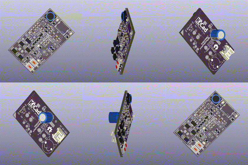
Ever wanted to charge your phone of your bikes dynamo? This Project does just that, for cheap (ish).
The incoming AC voltage from the dynamo gets rectified by 4 shottky-diodes and buffered in a high-capacity capacitor. Once a sufficient driving speed is reached and the capacitor is charged enough, the ATtiny1616 MCU on the board wakes up.
It measures the frequency of incoming AC voltage, which is corrolated to the driving speed, until it reaches the first threshold. Once the first threshold is reached, it can be assumed that enough power is available to charge the phone at 2.5W. The MCU enables the high efficiency DC/DC-Converter IC to generate 5V at the USB Type C Port. The pull-ups in the FUSB302 IC are set to signal to the attached device that 2.5W (500mA) are available. This prevents constant starting and stopping of the charging process, which is annoying. If the frequency is high enough to reach the 5W or 7.5W thresholds, 5W or 7.5W will be signaled via USB C power delivery.
If the device detects a DC source, it enters configuration mode. In configuration mode, the 2 buttons are used to select which threshold to calibrate. Connecting it back to a bike dynamo, it is now in calibration mode. The MCU will detect the needed speed to generate enough power for the prev. selected power level by connecting a 3W, 6W, or 9W constant power load and driving at a steadily increasing speed. Once the PowerGood signal does not drop out for 5 seconds with the load connected, a sufficient speed has been reached and is saved to EEPROM.

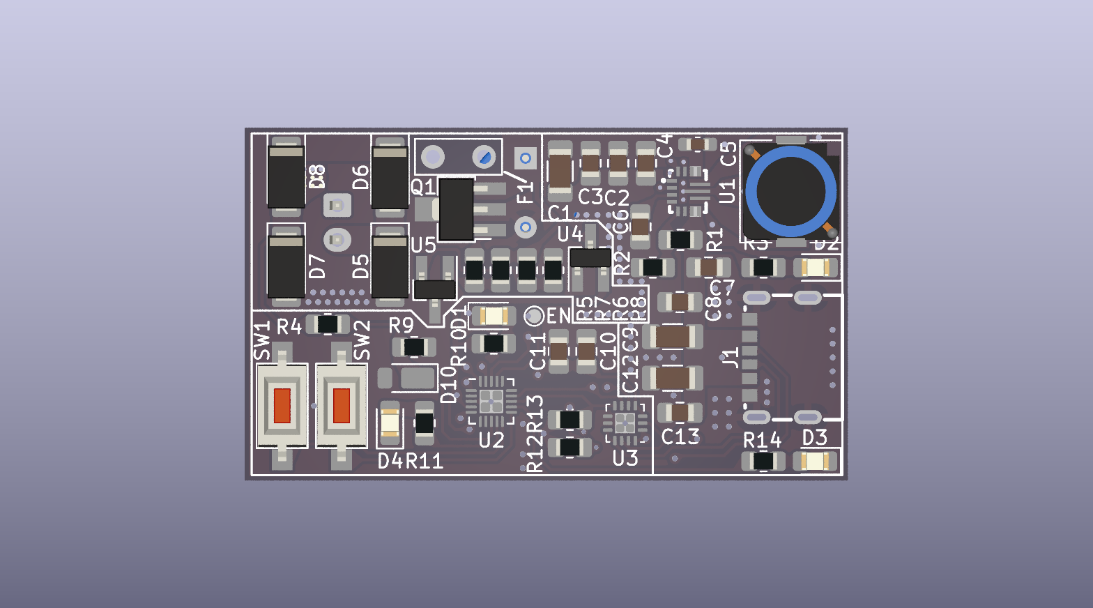
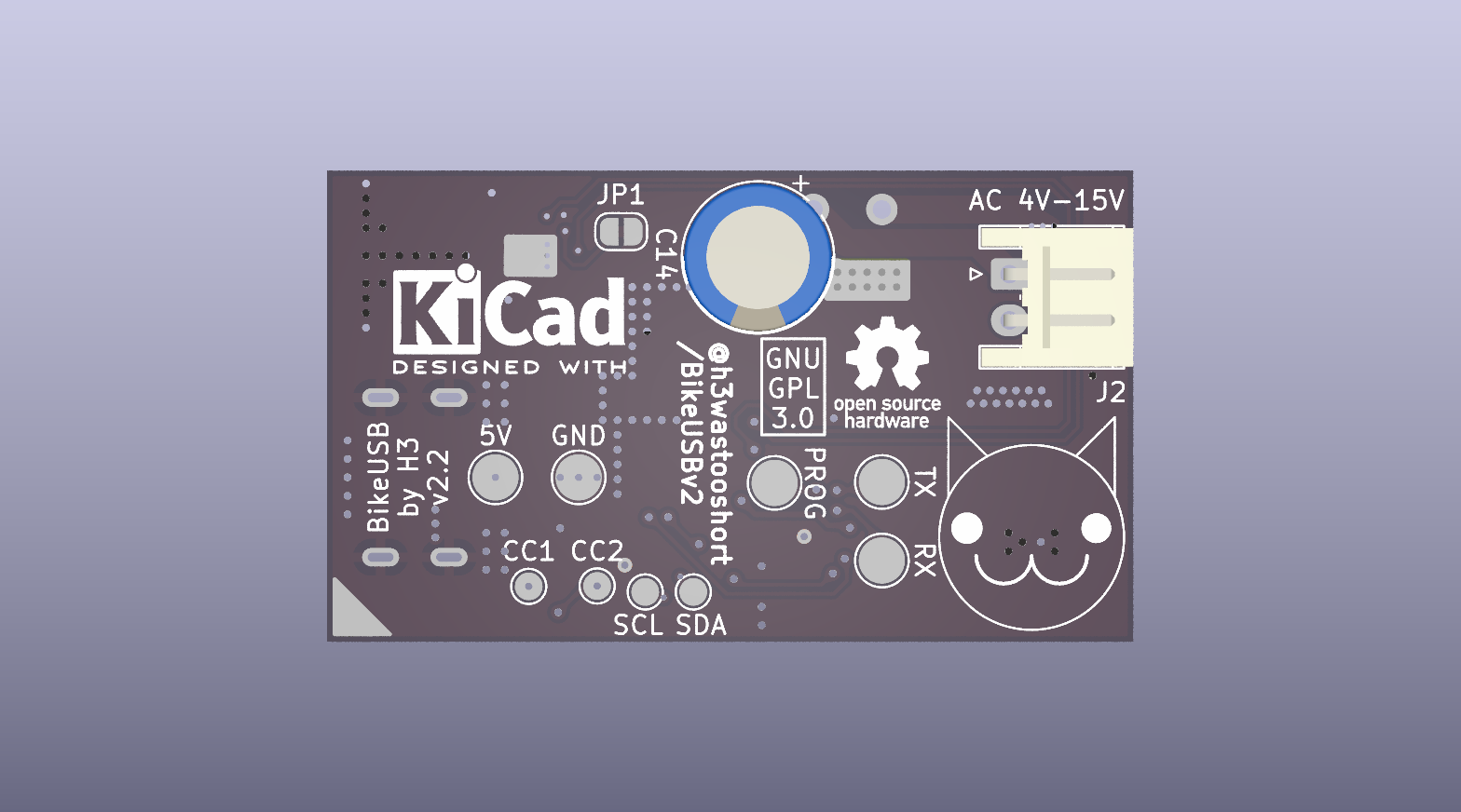
| Qty | Value | Footprint | References |
|---|---|---|---|
| 6 | 1k | Resistor_SMD:R_0805_2012Metric_Pad1.20x1.40mm_HandSolder | R3, R5, R7, R10, R11, R14 |
| 5 | 4u7 | Capacitor_SMD:C_0805_2012Metric_Pad1.18x1.45mm_HandSolder | C2, C3, C8, C10, C13 |
| 4 | 100n | Capacitor_SMD:C_0805_2012Metric_Pad1.18x1.45mm_HandSolder | C4, C6, C7, C11 |
| 4 | CMS04(TE12L,Q,M) | Diode_SMD:D_SOD-128 | D5, D6, D7, D8 |
| 3 | 22u | Capacitor_SMD:C_1206_3216Metric_Pad1.33x1.80mm_HandSolder | C1, C9, C12 |
| 2 | 1TS002E-2500-2501-CT | Button_Switch_SMD:SW_SPST_CK_RS282G05A3 | SW1, SW2 |
| 2 | 27k | Resistor_SMD:R_0805_2012Metric_Pad1.20x1.40mm_HandSolder | R1, R4 |
| 2 | 3k | Resistor_SMD:R_0805_2012Metric_Pad1.20x1.40mm_HandSolder | R2, R9 |
| 2 | 4k7 | Resistor_SMD:R_0805_2012Metric_Pad1.20x1.40mm_HandSolder | R12, R13 |
| 1 | 100n | Capacitor_SMD:C_0603_1608Metric_Pad1.08x0.95mm_HandSolder | C5 |
| 1 | 130k | Resistor_SMD:R_0805_2012Metric_Pad1.20x1.40mm_HandSolder | R6 |
| 1 | 24k | Resistor_SMD:R_0805_2012Metric_Pad1.20x1.40mm_HandSolder | R8 |
| 1 | 2SB772SQ | Package_TO_SOT_SMD:SOT-89-3_Handsoldering | Q1 |
| 1 | 4700µF | Capacitor_THT:CP_Radial_D8.0mm_P5.00mm | C14 |
| 1 | 5V | TestPoint:TestPoint_Pad_D2.5mm | TP2 |
| 1 | 76°C | H3_Other:SETfuse X-Series | F1 |
| 1 | ATtiny1616-M | Package_DFN_QFN:VQFN-20-1EP_3x3mm_P0.4mm_EP1.7x1.7mm | U2 |
| 1 | CC1 | TestPoint:TestPoint_Pad_D1.5mm | TP6 |
| 1 | CC2 | TestPoint:TestPoint_Pad_D1.5mm | TP7 |
| 1 | EN | TestPoint:TestPoint_Pad_D1.0mm | TP1 |
| 1 | FUSB302B10MPX | Package_DFN_QFN:WQFN-14-1EP_2.5x2.5mm_P0.5mm_EP1.45x1.45mm | U3 |
| 1 | GND | TestPoint:TestPoint_Pad_D2.5mm | TP3 |
| 1 | HT7550 | Package_TO_SOT_SMD:SOT-23_Handsoldering | U4 |
| 1 | JST S2B-EH(LF)(SN) | Connector_JST:JST_EH_S2B-EH_1x02_P2.50mm_Horizontal | J2 |
| 1 | PCBcat | H3_Other:PCBcat | CAT** |
| 1 | PROG | TestPoint:TestPoint_Pad_D2.5mm | TP4 |
| 1 | RX | TestPoint:TestPoint_Pad_D2.5mm | TP10 |
| 1 | SCL | TestPoint:TestPoint_Pad_D1.5mm | TP9 |
| 1 | SDA | TestPoint:TestPoint_Pad_D1.5mm | TP8 |
| 1 | SolderJumper_2_Bridged | Jumper:SolderJumper-2_P1.3mm_Bridged_RoundedPad1.0x1.5mm | JP1 |
| 1 | TL431AIDBZR | Package_TO_SOT_SMD:SOT-23_Handsoldering | U5 |
| 1 | TPS63070 | e2k_edit:VQFN-HR-15_L3.0-W2.5-P0.50-BL_TPS63070RNMR | U1 |
| 1 | TX | TestPoint:TestPoint_Pad_D2.5mm | TP5 |
| 1 | TYPE-C-31-M-16 | easyeda2kicad:TYPE-C-SMD_TYPE-C-31-M-16 | J1 |
| 1 | XL-2012SURC | LED_SMD:LED_0805_2012Metric_Pad1.15x1.40mm_HandSolder | D4 |
| 1 | XL-2012UBC | LED_SMD:LED_0805_2012Metric_Pad1.15x1.40mm_HandSolder | D3 |
| 1 | XL-2012UGC | LED_SMD:LED_0805_2012Metric_Pad1.15x1.40mm_HandSolder | D2 |
| 1 | XL-2012UOC | LED_SMD:LED_0805_2012Metric_Pad1.15x1.40mm_HandSolder | D1 |
| 1 | YPRH0704-1R0M | Inductor_SMD:L_7.3x7.3_H4.5 | L1 |
| 1 | ~ | Diode_SMD:D_PowerDI-123 | D10 |
The 61 most common of 63 parts.

H3wastooshort/the_extender
it extends your phones storage, battery life, and audio interfaces

loozhengyuan/MitsubishiSC
Smart controller for Mitsubishi Electric HVAC systems.

grepson/smart-lamps-pcb
A smart lamp pcb that is designed to run little chain of WS LED's with Li-Ion battery support

JamPsym/letki
A new schematic simplification is in progress. See the next-iteration note for the checked 33 Ω candidate. This directory and its frozen exports still represent the previous 34 Ω circuit; the candidate has no…


zeankundev/boards
A collection and an archive of KiCad projects I made. Contains projects from 2023 - 2024.
It measures 43.6 × 25.5 mm and has 2 copper layers, 1.6 mm thick.
63 parts, built around the ATTINY1616-MN, FUSB302B10MPX, TPS63070RNM and HT7550. The full list of its parts is on this page, with links to each part's symbol and footprint where PCBKit's library has them.
From the H3wastooshort/BikeUSBv2 repository on GitHub, at the commit this page was made from: the board is hardware/BikeUSBv2.kicad_pcb and its schematic hardware/BikeUSBv2.kicad_sch. PCBKit opens the board in the browser, with nothing to install.
Its repository publishes it under the GPL-3.0 licence: you may reuse it on that licence's terms (keep the author's notice, and for a copyleft licence share your changes alike).