4 layers21 × 31 mm
Ant control board v2
FloppyO1/Floppy-Ant-Controller
The FAC Tool provides a graphical interface for granular control over your robot's behavior:
97 parts2CERN-OHL-S-2.0

 FloppyO1/Floppy-Ant-Controller2
The FAC Tool provides a graphical interface for granular control over your robot's behavior:
Ant control board v2 is an open-source printed circuit board by FloppyO1, from the FloppyO1/Floppy-Ant-Controller repository on GitHub, published under the CERN-OHL-S-2.0 licence. It is a 2-layer board of 65 × 60 mm with 102 parts on 60 nets, routed with 467 tracks and 75 vias.
It is built around the NRF24L01, DRV8837DSG and AT24C02CN, with the GM7333K, LSM6DS3 and SD103AWS among its other parts. Its parts include 23 capacitors, 11 connectors, 9 ICs, 8 resistors and 2 diodes. It belongs with the STM32 boards of this library.


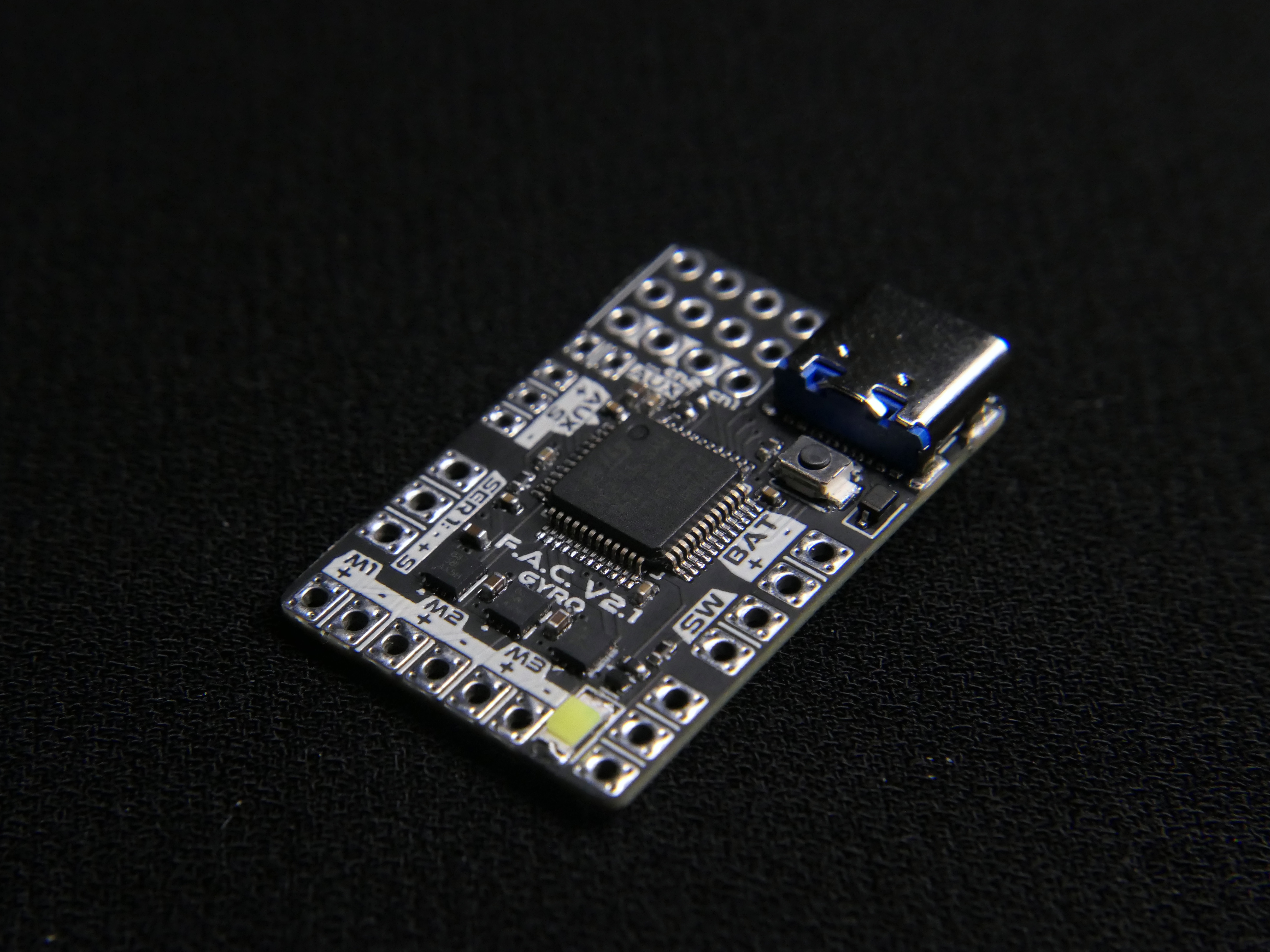
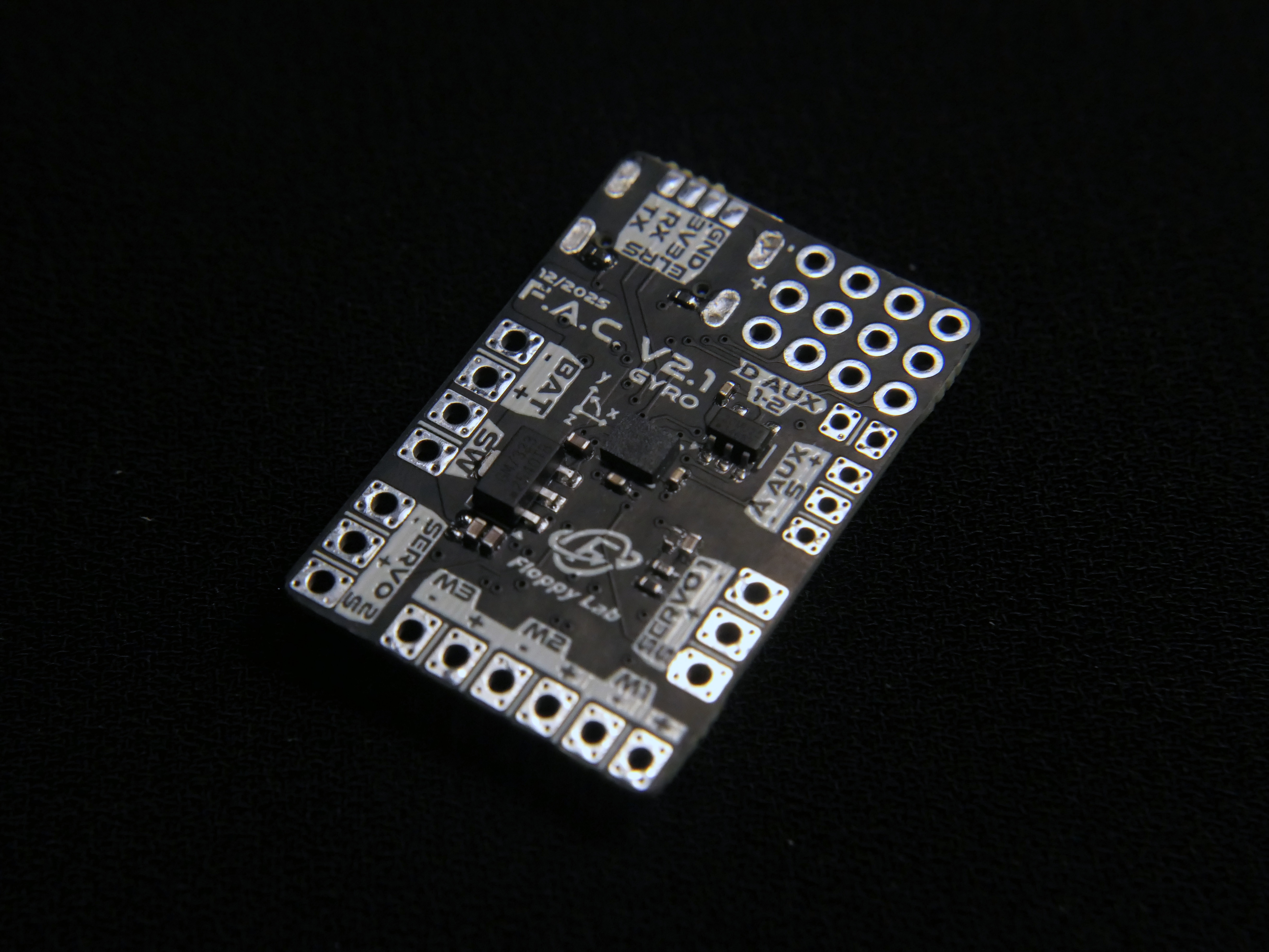
F.A.C. V2 is an advanced control board specifically designed for combat robots (such as the Antweight category). Created by Floppy Lab, it serves as a high-performance, highly customizable alternative to the Malenki-nano, offering professional features at a competitive price point.
Full Customization: All parameters are adjustable via USB using the dedicated FAC Tool.
Advanced Hardware: Features a built-in IMU (accelerometer and gyroscope) for future firmware updates and advanced control algorithms.
Open Source: Built with a community-first approach, allowing for user modifications and contributions.
Robust Safety: Includes integrated Watchdog timers, Fail-Safe mechanisms, and Battery Cut-Off to protect your hardware.
DC Motor Outputs: 3 channels (1.8A max, 1000-step resolution, adjustable frequency 100Hz-10kHz).
Servo Outputs: 2 HV channels (powered directly by the battery) with adjustable frequency and pulse width.
Inputs: 2 Digital inputs and 1 Analog input (max 3.3V).
Power Supply: Optimized for 1-2S LiPo batteries (up to 11V max).
Compact Form Factor: 21mm x 31mm; weighs only 2.4g (bare board) 3.6g (with FS2A).
Receiver Compatibility: Supports PWM (up to 4 channels) and PPM (up to 8 channels), ELRS (not implemented yet but ready to run on current hardware).
The FAC Tool provides a graphical interface for granular control over your robot's behavior:
Mapping: Freely assign software functions (e.g., Tank Mix) to physical pins on the board.
Mixes & Special Functions: Easily configure steering mixes or direct links between radio channels and outputs and others like DC servo.
Real-time Telemetry: Monitor battery voltage, radio signal values, and operational status (Armed/Disarmed/Cut-Off).
Reverse Polarity: The board does not have reverse polarity protection. Ensure the battery is connected correctly to avoid permanent damage.
Activation: For safety, the FAC will not activate until it detects a valid signal from your receiver.
Battery Management: Always configure the Battery Cut-Off to prevent over-discharging your LiPo cells.
/FIRMWARE V2: Firmware source code and binaries.
/docs: Full English and Italian manual.
/HARDWARE V2: Design files.
/TOOLS: Usefull python tools, and the FAC jingle composer.
If you want to manufacture them by yourself you can do it directly from this link: click here
Using this link you automatically help me with a small tip, without any additional costs. Thanks!
Developed by Floppy Lab™. For suggestions, bugs, or feedback:
Email: thefloppylab@gmail.com
Instagram: @the_floppy_lab
YouTube: @floppylab
Website: www.floppylab.it
© 2026 The Floppy Lab™. All rights reserved.
| Qty | Value | Footprint | References |
|---|---|---|---|
| 13 | 100n | Capacitor_SMD:C_0603_1608Metric | C5, C7, C9, C12, C13, C14, C15, C17, C18, C19, C20, C21, C22 |
| 10 | 4.7u | Capacitor_SMD:C_0603_1608Metric | C1, C2, C3, C4, C6, C8, C10, C11, C16, C23 |
| 4 | 5.1k | Resistor_SMD:R_0603_1608Metric | R4, R6, R7, R8 |
| 4 | MountingHole | MountingHole:MountingHole_2.2mm_M2_Pad_Via | H1, H2, H3, H4 |
| 3 | DRV8837 | Package_SON:WSON-8-1EP_2x2mm_P0.5mm_EP0.9x1.6mm | U2, U3, U4 |
| 2 | 1.5k | Resistor_SMD:R_0603_1608Metric | R2, R5 |
| 2 | 10k | Resistor_SMD:R_0603_1608Metric | R1, R3 |
| 1 | 2s Battery | Connector_PinHeader_2.54mm:PinHeader_1x02_P2.54mm_Vertical | J2 |
| 1 | 3V3 | TestPoint:TestPoint_THTPad_1.5x1.5mm_Drill0.7mm | TP1 |
| 1 | ADC_AUX | Connector_PinHeader_2.54mm:PinHeader_1x03_P2.54mm_Vertical | J8 |
| 1 | AT24C02C | Package_TO_SOT_SMD:SOT-23-5 | U8 |
| 1 | BOOT | Button_Switch_SMD:SW_SPST_CK_RS282G05A3 | SW1 |
| 1 | DIGITAL_AUX | Connector_PinHeader_2.54mm:PinHeader_1x02_P2.54mm_Vertical | J9 |
| 1 | ELRS | Connector_PinSocket_2.54mm:PinSocket_1x04_P2.54mm_Vertical | J10 |
| 1 | FS2A 4CH reciever | _My_modules:FS2A 4CH reciever | U7 |
| 1 | G*** | kibuzzard-68591BA8 | kibuzzard-68591BA8 |
| 1 | G*** | kibuzzard-68590DB3 | kibuzzard-68590DB3 |
| 1 | G*** | kibuzzard-68591BA5 | kibuzzard-68591BA5 |
| 1 | G*** | kibuzzard-6859111F | kibuzzard-6859111F |
| 1 | G*** | kibuzzard-68590E35 | kibuzzard-68590E35 |
| 1 | G*** | kibuzzard-68591131 | kibuzzard-68591131 |
| 1 | G*** | kibuzzard-68590DCB | kibuzzard-68590DCB |
| 1 | G*** | kibuzzard-68590F5B | kibuzzard-68590F5B |
| 1 | G*** | kibuzzard-68590F1F | kibuzzard-68590F1F |
| 1 | G*** | kibuzzard-6859119B | kibuzzard-6859119B |
| 1 | G*** | kibuzzard-68590E57 | kibuzzard-68590E57 |
| 1 | G*** | kibuzzard-6859170A | kibuzzard-6859170A |
| 1 | G*** | kibuzzard-685911E8 | kibuzzard-685911E8 |
| 1 | G*** | kibuzzard-68591192 | kibuzzard-68591192 |
| 1 | G*** | kibuzzard-68591152 | kibuzzard-68591152 |
| 1 | G*** | kibuzzard-68590DE3 | kibuzzard-68590DE3 |
| 1 | G*** | kibuzzard-6859100F | kibuzzard-6859100F |
| 1 | G*** | kibuzzard-68590F79 | kibuzzard-68590F79 |
| 1 | G*** | kibuzzard-6859102F | kibuzzard-6859102F |
| 1 | G*** | kibuzzard-68590DDD | kibuzzard-68590DDD |
| 1 | G*** | kibuzzard-68591071 | kibuzzard-68591071 |
| 1 | G*** | kibuzzard-68591B9B | kibuzzard-68591B9B |
| 1 | G*** | kibuzzard-68591B85 | kibuzzard-68591B85 |
| 1 | G*** | kibuzzard-68591112 | kibuzzard-68591112 |
| 1 | G*** | kibuzzard-68590E11 | kibuzzard-68590E11 |
| 1 | G*** | kibuzzard-685910F4 | kibuzzard-685910F4 |
| 1 | G*** | kibuzzard-6859109F | kibuzzard-6859109F |
| 1 | G*** | kibuzzard-6859112C | kibuzzard-6859112C |
| 1 | G*** | kibuzzard-68591052 | kibuzzard-68591052 |
| 1 | G*** | kibuzzard-68591123 | kibuzzard-68591123 |
| 1 | G*** | kibuzzard-685911EF | kibuzzard-685911EF |
| 1 | G*** | kibuzzard-68590DA6 | kibuzzard-68590DA6 |
| 1 | G*** | kibuzzard-685916F6 | kibuzzard-685916F6 |
| 1 | GM7333 | Package_TO_SOT_SMD:SOT-89-3 | U1 |
| 1 | GND | TestPoint:TestPoint_THTPad_1.5x1.5mm_Drill0.7mm | TP2 |
| 1 | LOGO | LOGO | G*** |
| 1 | LSM6DS3 | Package_LGA:LGA-14_3x2.5mm_P0.5mm_LayoutBorder3x4y | U5 |
| 1 | M1 | Connector_PinHeader_2.54mm:PinHeader_1x02_P2.54mm_Vertical | J3 |
| 1 | M1 IN1 | TestPoint:TestPoint_THTPad_1.5x1.5mm_Drill0.7mm | TP3 |
| 1 | M1 IN2 | TestPoint:TestPoint_THTPad_1.5x1.5mm_Drill0.7mm | TP4 |
| 1 | M2 | Connector_PinHeader_2.54mm:PinHeader_1x02_P2.54mm_Vertical | J4 |
| 1 | M2 IN1 | TestPoint:TestPoint_THTPad_1.5x1.5mm_Drill0.7mm | TP5 |
| 1 | M2 IN2 | TestPoint:TestPoint_THTPad_1.5x1.5mm_Drill0.7mm | TP6 |
| 1 | M3 | Connector_PinHeader_2.54mm:PinHeader_1x02_P2.54mm_Vertical | J5 |
| 1 | M3 IN1 | TestPoint:TestPoint_THTPad_1.5x1.5mm_Drill0.7mm | TP7 |
| 1 | M3 IN2 | TestPoint:TestPoint_THTPad_1.5x1.5mm_Drill0.7mm | TP8 |
| 1 | NRF24L01 | _My_modules:NRF24L01+ SMD | U9 |
| 1 | S1 | TestPoint:TestPoint_THTPad_1.5x1.5mm_Drill0.7mm | TP9 |
| 1 | S2 | TestPoint:TestPoint_THTPad_1.5x1.5mm_Drill0.7mm | TP10 |
| 1 | SD103AWS | Diode_SMD:D_SOD-123 | D1 |
| 1 | ST-LINK | Connector_PinHeader_2.54mm:PinHeader_1x05_P2.54mm_Vertical | J11 |
| 1 | STATUS | LED_SMD:LED_0805_2012Metric | D2 |
| 1 | STM32F072CBTx | Package_QFP:LQFP-48_7x7mm_P0.5mm | U6 |
| 1 | USB-C_304A-ACP16X | _MIA footprint:USB_C_304A-ACP16X | J1 |
| 1 | servo 1 | Connector_PinHeader_2.54mm:PinHeader_1x03_P2.54mm_Vertical | J6 |
| 1 | servo 2 | Connector_PinHeader_2.54mm:PinHeader_1x03_P2.54mm_Vertical | J7 |
FloppyO1/Floppy-Ant-Controller
The FAC Tool provides a graphical interface for granular control over your robot's behavior:

FloppyO1/Floppy-Ant-Controller
The FAC Tool provides a graphical interface for granular control over your robot's behavior:

FloppyO1/Floppy-Ant-Controller
The FAC Tool provides a graphical interface for granular control over your robot's behavior:

FloppyO1/Floppy-Ant-Controller
The FAC Tool provides a graphical interface for granular control over your robot's behavior:

gkhnmlym/RP2040
"RP2040 is a microcontroller chip developed by Raspberry Pi, based on the ARM Cortex-M0+ core. This chip has gained popularity due to several advantages, especially for embedded systems and microcontroller projects.


pms67/HadesFCS
Complete flight control system designed from scratch. Hardware designed with KiCad.

jackw01/scanlight
A better light source for scanning color negative film


It measures 65 × 60 mm and has 2 copper layers, 1.6 mm thick.
102 parts, built around the NRF24L01, DRV8837DSG, AT24C02CN and GM7333K. The full list of its parts is on this page, with links to each part's symbol and footprint where PCBKit's library has them.
From the FloppyO1/Floppy-Ant-Controller repository on GitHub, at the commit this page was made from: the board is HARDWARE V2/DEVELOPMENT/ant control board v2 development board/ant control board v2.kicad_pcb and its schematic HARDWARE V2/DEVELOPMENT/ant control board v2 development board/MCU_RX.kicad_sch. PCBKit opens the board in the browser, with nothing to install.
Its repository publishes it under the CERN-OHL-S-2.0 licence: you may reuse it on that licence's terms (keep the author's notice, and for a copyleft licence share your changes alike).