2 layers50 × 35 mm

 Fescron/Ultimate_Adafruit_MacroPad5
An upgraded Adafruit Macropad with easier macro-layer-switching using additional NeoKey buttons (and OLED display). Also includes keyboard-layout switching and dimming as well as a lot of macro-definitions.
Ultimate adafruit macropad baseboard is an open-source printed circuit board by Fescron, from the Fescron/Ultimate_Adafruit_MacroPad repository on GitHub, published under the MIT licence. It is a 2-layer board of 105.4 × 107.9 mm with 17 parts on 12 nets, routed with 22 tracks and 0 vias.
It belongs with the keyboards and input and lEDs and displays boards and the RP2040 boards of this library.



This repository contains necessary components and fabrication instructions for my Ultimate Adafruit Macropad, as well as the code and macro-definitions I run on it. Configuration and usage instructions are also listed here.
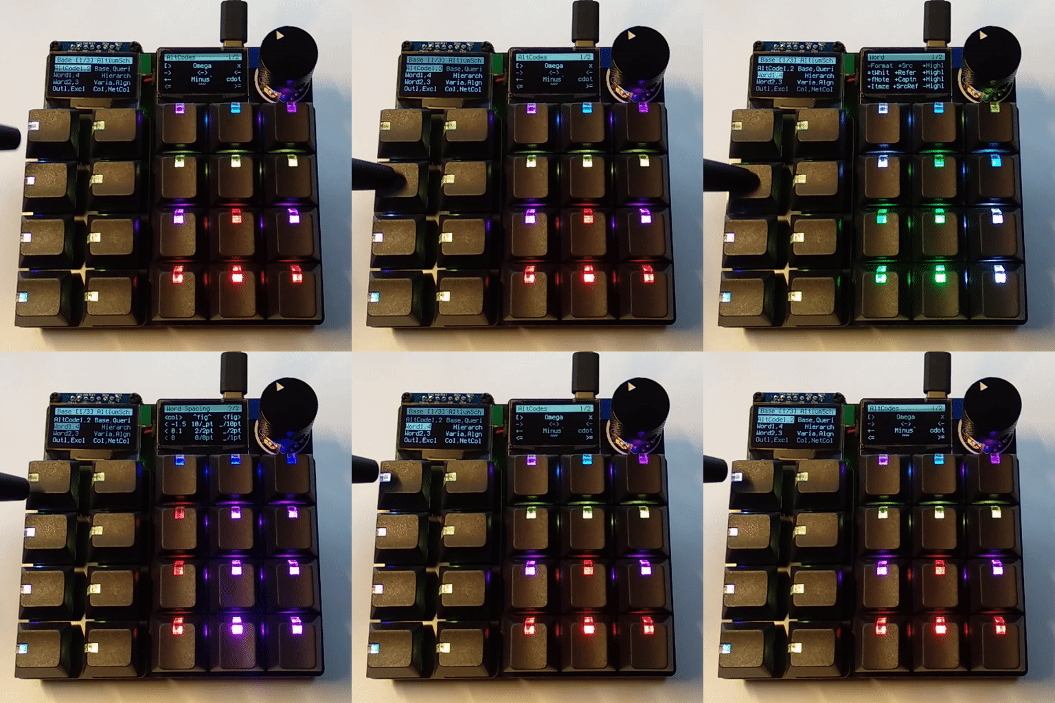
I've basically added two NeoKey 1x4 boards next to the Adafruit Macropad to simplify macro-layer-switching. I've found that pressing a button to change a macro-layer on the Macropad is much faster than rotating the encoder, certainly if there are (currently) more than 25 layers defined. The encoder is repurposed to change macro-selection-layers on the NeoKey buttons. To have an additional (apart from the button color) indication of what Macropad layer can be activated using a specific NeoKey button, I've also added a 1.3" 128x64 OLED display above the NeyKey boards.
I've subsequently (heavily) modified the original Macropad Hotkeys code to work with these additional buttons and display, as wel as added functionality to use other keyboard layouts (using code from this repository) and to dim the displays and button-LEDs after some time (using code from this repository). Since the default firmware on the Macropad doesn't support two displays I've also had to compile new CircuitPython firmware to flash to the Macropad.
| Folder | Contents |
|---|---|
CIRCUITPY | All files as-is on my Ultimate Adafruit Macropad. It contains libraries (lib), macros (macros), the main code.py-file, a quick reference to keycodes (Keycodes.txt) and a VSCode workspace (workspace.code-workspace) to quickly open some files to I can edit them. |
img | Images displayed on this README. |
pcb | Two (custom) KiCad PCBs to assemble the Ultimate Adafruit Macropad. |
uf2 | A CircuitPython firmware-file for the Adafruit Macropad with support for two screens. |
The Ultimate Adafruit Macropad is constructed using the materials from the tables below. Note that my version is very fancy, with very expensive (but amazing looking) windowed keycaps. These are certainly not required, and instead an Adafruit MacroPad RP2040 Starter Kit with included basic keycaps and switches can also be purchased.
Also note that the NeoKey 1x4 boards ship without switches and keycaps, they need to be purchased separately. In case the Adafruit MacroPad RP2040 Starter Kit is bought (instead of the Adafruit MACROPAD RP2040 Bare Bones board) individual switches and keycaps still need to be purchased for the NeoKey boards.
| Qty | Description | Link |
|---|---|---|
| 1 | Adafruit MACROPAD RP2040 Bare Bones | https://www.adafruit.com/product/5100 |
| 2 | Kailh Mechanical Key Switches - Tactile Brown - 10 pack | https://www.adafruit.com/product/4954 |
| 2 | NeoKey 1x4 QT I2C | https://www.adafruit.com/product/4980 |
| 20 | Black Windowed Lamp R4 Keycap for MX Compatible Switches | https://www.adafruit.com/product/5112 |
| 1 | STEMMA QT / Qwiic JST SH 4-Pin Cable - 50mm Long | https://www.adafruit.com/product/4399 |
| 1 | Monochrome 1.3" 128x64 OLED graphic display - STEMMA QT / Qwiic | https://www.adafruit.com/product/938 |
| 1 | Anodized Aluminum Machined Knob - Black - 20mm Diameter | https://www.adafruit.com/product/5527 |
| 1 | Adafruit MacroPad RP2040 Enclosure + Hardware Add-on Pack | https://www.adafruit.com/product/5103 |
| 1 | Baseboard PCB | (see these gerber-files) |
| 1 | Keyplate PCB | (see these gerber-files) |
Additionally some more generic items are necessary and/or can be useful.
| Description | Usage | Link(s) |
|---|---|---|
| Male (and female) 2.54mm/0.1" pinheaders | Mounting the NeoKey and OLED boards to the Baseboard PCB | https://www.adafruit.com/product/392 https://www.adafruit.com/product/598 |
| Black Nylon Machine Screw and Stand-off Set - M2.5 Thread | Mounting the NeoKey and OLED boards to the Baseboard PCB | https://www.adafruit.com/product/3299 |
| Black Nylon Machine Screw and Stand-off Set - M3 Thread | Mounting the Macropad to the Boaseboard PCB | https://www.adafruit.com/product/4685 |
| 2 pcs Laptop riser feet | Setting the board on an angle for easier usage | https://www.aliexpress.com/item/1005003557570061.html |
| 12x5mm 40 pcs round rubber pads | Making sure the board doesn't slide around | https://www.aliexpress.com/item/33030992785.html |
| Carrying case | Protecting the board during travel | https://www.aliexpress.com/item/1005001855670902.html |
As the last two entries in the first material-table already suggested, I've also designed two custom PCBs to facilitate a fairly easy assembly and final sturdy device. The Baseboard PCB is used to mount all boards to a single PCB, while also facilitating some interconnections between the components. Only a single Stemma QT / Qwiic cable (in an out-of-sight spot) is required, the rest of the connections are done by the Baseboard.
The second PCB, the Keyplace PCB, is used to secure the eight mechanical switches to the two NeoKey boards. It basically has the same functionality as the keyplace-PCB does for the Adafruit Macropad (included in the Adafruit MacroPad RP2040 Enclosure + Hardware Add-on Pack or Adafruit MacroPad RP2040 Starter Kit).
A0 of the left-most NeoKey 1x4 board to set its I2C address to 0x31. The right-most NeoKey 1x4 board will keep its default address of 0x30.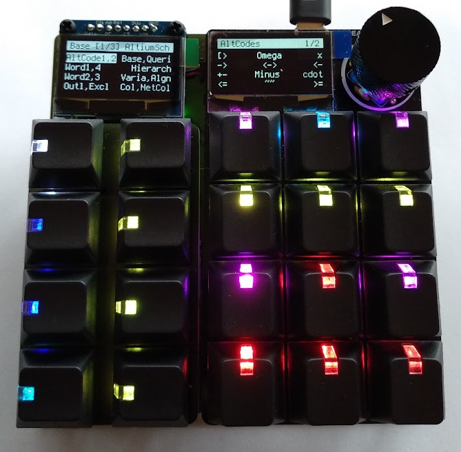 | 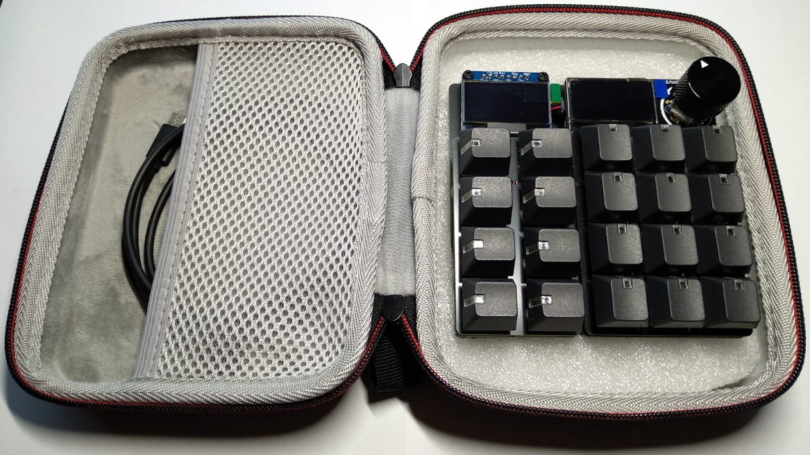 |
|---|
As already mentioned, the default CircuitPython firmware for the Adafruit Macropad doesn't support two screens. Fortunately it is possible to build .uf2-files yourself which do support this. The result of this is placed in the uf2 directory on this repository.
## https://learn.adafruit.com/building-circuitpython/linux
# Install additional software
sudo apt install build-essential
sudo add-apt-repository ppa:git-core/ppa
sudo add-apt-repository ppa:pybricks/ppa
# Download the appropriate ARM Cortex-M toolchain
# (for CircuitpPython 8.x: 10-2020-q4-major https://developer.arm.com/downloads/-/gnu-rm)
# Unpack it in a convenient directory
mkdir ~/bin
cd ~/bin
tar xvf gcc-arm-none-eabi-10-2020-q4-major-x86_64-linux.tar.bz2
# Add a link to the toolchain executables in PATH
sudo nano ~/.profile
  export PATH=/home/$USER/bin/gcc-arm-none-eabi-10-2020-q4-major/bin:$PATH
# Logout and log back in
# Check if the link is correctly configured
which arm-none-eabi-gcc

## https://learn.adafruit.com/building-circuitpython/build-circuitpython
# Clone the repository
git clone https://github.com/adafruit/circuitpython.git
cd circuitpython
# Install needed Python packages from pypi.org.
pip3 install --upgrade -r requirements-dev.txtRPI-RP2 drive shows up on the computer..uf2-file to the RPI-RP2 driveAfter the firmware has been updated, the necessary libraries (and other files) need to be copied to the (Ultimate) Adafruit Macropad. One can simply copy all contents inside the CIRCUITPY directory of this repository to the Macropad.
If all of the necessary files are copied to the Macropad, the customization can begin. CIRCUITPY/code.py is the main configuration file. The macro-definitions can be found in CIRCUITPY/macros. All of the files start with a number so they are sorted in a specific order. The number is also used to configure the NeoKey layers (NEOKEY_BUTTONS).
Inside CIRCUITPY/code.py are a few configuration-variables to change some functionality.
KEYBOARD_LAYOUT
KEYBOARD_LAYOUT = 0: Select US QWERTY as keyboard layout.KEYBOARD_LAYOUT = 1: Select Belgian AZERTY as keyboard layout (default).KEYBOARD_LAYOUT = 2: Select my Custom Belgian AZERTY keyboard layout where the numbers and characters on the number-row are swapped around.MACRO_FOLDER
MACRO_FOLDER = '/macros': Select the folder where the code looks for macro-definitions.NEOKEY_BUTTONS_START_LAYER: Select the start-up NeoKey button-layer.NEOKEY_BUTTONS_START_BUTTON: Select the start-up NeoKey button.NEOKEY_BUTTONS
CIRCUITPY/macros.
(0x000000, "", [0]),TIMEOUT_S
TIMEOUT_S = 10 * 60: Set the timeout to 10 minutes, after which the OLED displays and button-LEDs will dim. All button-functionality however still remains active.NEOKEY_BUTTONS = [
[
# Layer title
"Base [1/3] AltiumSch",
# Button definitions
[
# First row
(0x004000, "AltCode1,2", [0, 1]), # Alt-codes 1 & 2
(0x404000, "Base,Queri", [3, 24]), # Altium Schematic 1 & Validation Queries
# Second row
(0x000040, "Word1,4", [2, 16]), # Word 1 & 4
(0x404000, "Hierarch", [4]), # Altium Schematic 2
# Third row
(0x000040, "Word2,3", [20, 23]), # Word 2 & 3
(0x404000, "Varia,Algn", [5, 22]), # Altium Schematic 3 & Alignment
# Fourth row
(0x004040, "Outl,Excl", [18, 26]), # Outlook & Excel
(0x404000, "Col,NetCol", [15, 11]) # Altium Colors & Net-colors
]
],
]The build-up of the macro-file definitions (CIRCUITPY/macros) is unchanged compared to those of a "regular" Adafruit Macropad, and thus can perfectly be used in a "barebones" setup. Because of this the syntax won't be explicitly explained here, only some "tricks" I used when defining my macro-files.
`-character at the front of a macro-label on the OLED display, it means a right-click mouse-action is used.`-character at the end of a macro-label on the OLED display, it means some sort of custom keyboard-shortcut was used. Or, in the case of the Altium color-pages, a non-standard color was defined.With the Ultimate Adafruit Macropad macro-definition-pages can be switched to by simply pressing one of the NeoKey buttons on the left of the Macropad, instead of rotating the encoder. The OLED display above the NeoKey buttons is used to show informating regarding these Macropad layers. The LED of the last selected (group of) page(s) lights up bright white, and the text on the OLED is inverted. The other NeoKey LEDs light up according to their defined color in NEOKEY_BUTTONS in the CIRCUITPY/code.py file.
The latter file is used to do the main configuration, such as defining which Macropad layers (placed in CIRCUITPY/macros) can be activated using which NeoKey buttons. When there are multiple macro-definition-pages linked to a single NeoKey button (more than one number in the square brackets in NEOKEY_BUTTONS), subsequent presses on the same key rotate between all pages defined in the list. The last selected page is remembered in case another NeoKey button is pressed to select another (group of) page(s), or a whole NeoKey layer is changed using the rotary encoder. The first line on the OLED display above the NeoKey buttons also shows a title of the current layer, which is also configured in CIRCUITPY/code.py.
| Qty | Value | Footprint | References |
|---|---|---|---|
| 10 | MountingHole | MountingHole:MountingHole_2.7mm_M2.5 | J1_H1, J1_H2, J1_H3, J1_H4, J2_H1, J2_H2, J2_H3, J2_H4, J3_H1, J3_H2 |
| 4 | MountingHole | MountingHole:MountingHole_3.2mm_M3 | H1, H2, H3, H4 |
| 2 | Conn_01x06 | Connector_PinSocket_2.54mm:PinSocket_1x06_P2.54mm_Vertical | J1, J2 |
| 1 | Conn_01x08 | Connector_PinSocket_2.54mm:PinSocket_1x08_P2.54mm_Vertical | J3 |


hoglet67/RGBtoHDMI
Bare-metal Raspberry Pi project that provides pixel-perfect sampling of Retro Computer RGB/YUV video and conversion to HDMI


hackclub/OnBoard
💡 Join 1,000 teenagers and make your first PCB with a $100 grant!

DDeGonge/OS-ARM
This arm is not industrial and it will not be fast, but that is not my goal. But it will hopefully be a very nice looking arm fully capable of 6dof motion, cheap enough to keep it accessable but capable enough to…


It measures 105.4 × 107.9 mm and has 2 copper layers, 1.6 mm thick.
17 parts. The full list of its parts is on this page, with links to each part's symbol and footprint where PCBKit's library has them.
From the Fescron/Ultimate_Adafruit_MacroPad repository on GitHub, at the commit this page was made from: the board is pcb/ultimate-adafruit-macropad-baseboard/ultimate-adafruit-macropad-baseboard.kicad_pcb and its schematic pcb/ultimate-adafruit-macropad-baseboard/ultimate-adafruit-macropad-baseboard.kicad_sch. PCBKit opens the board in the browser, with nothing to install.
Its repository publishes it under the MIT licence: you may reuse it on that licence's terms (keep the author's notice, and for a copyleft licence share your changes alike).