
4 layers35 × 40 mm

A PWM Solar Charge controller based on Julian Lietts PWM5
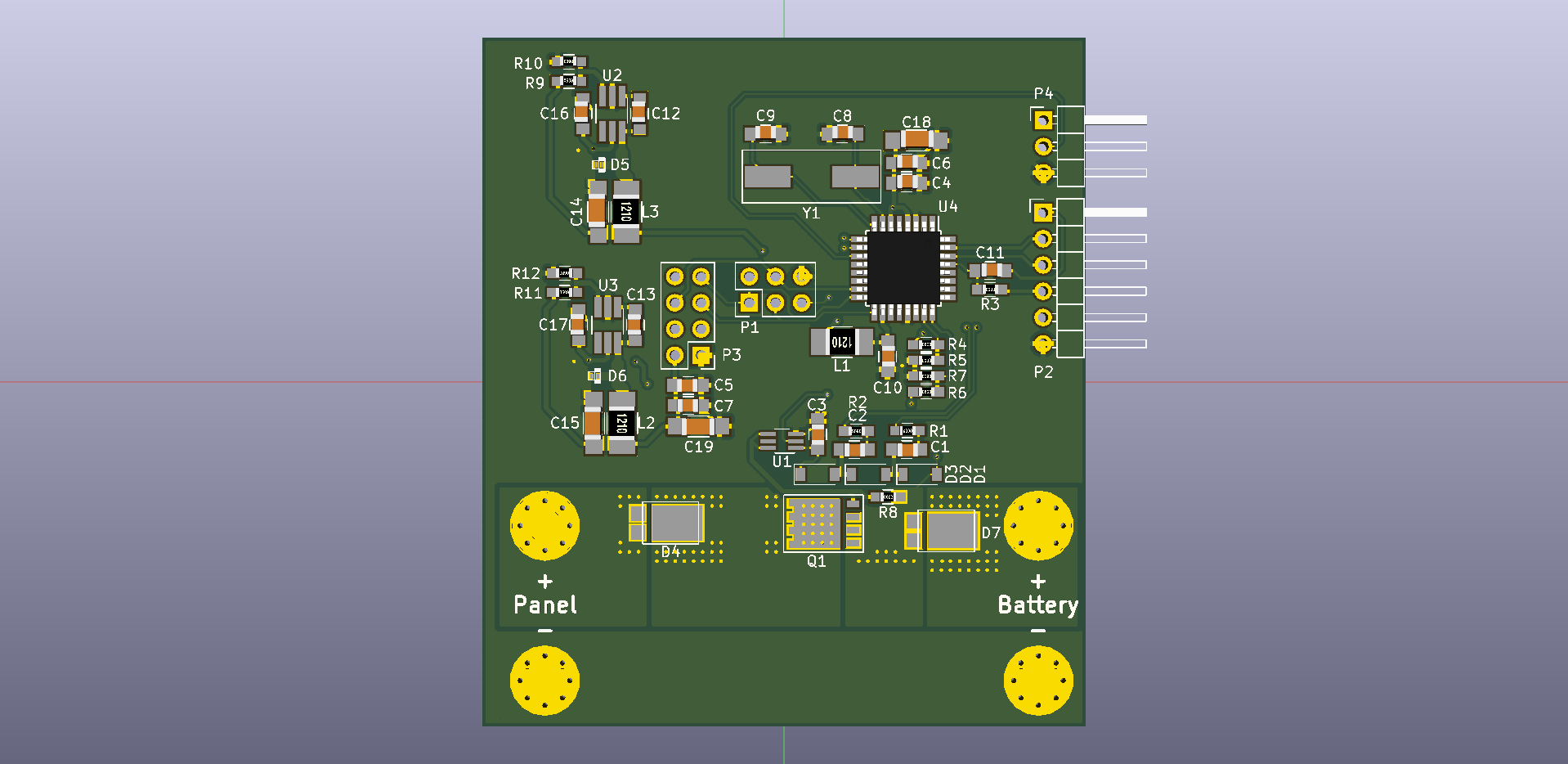
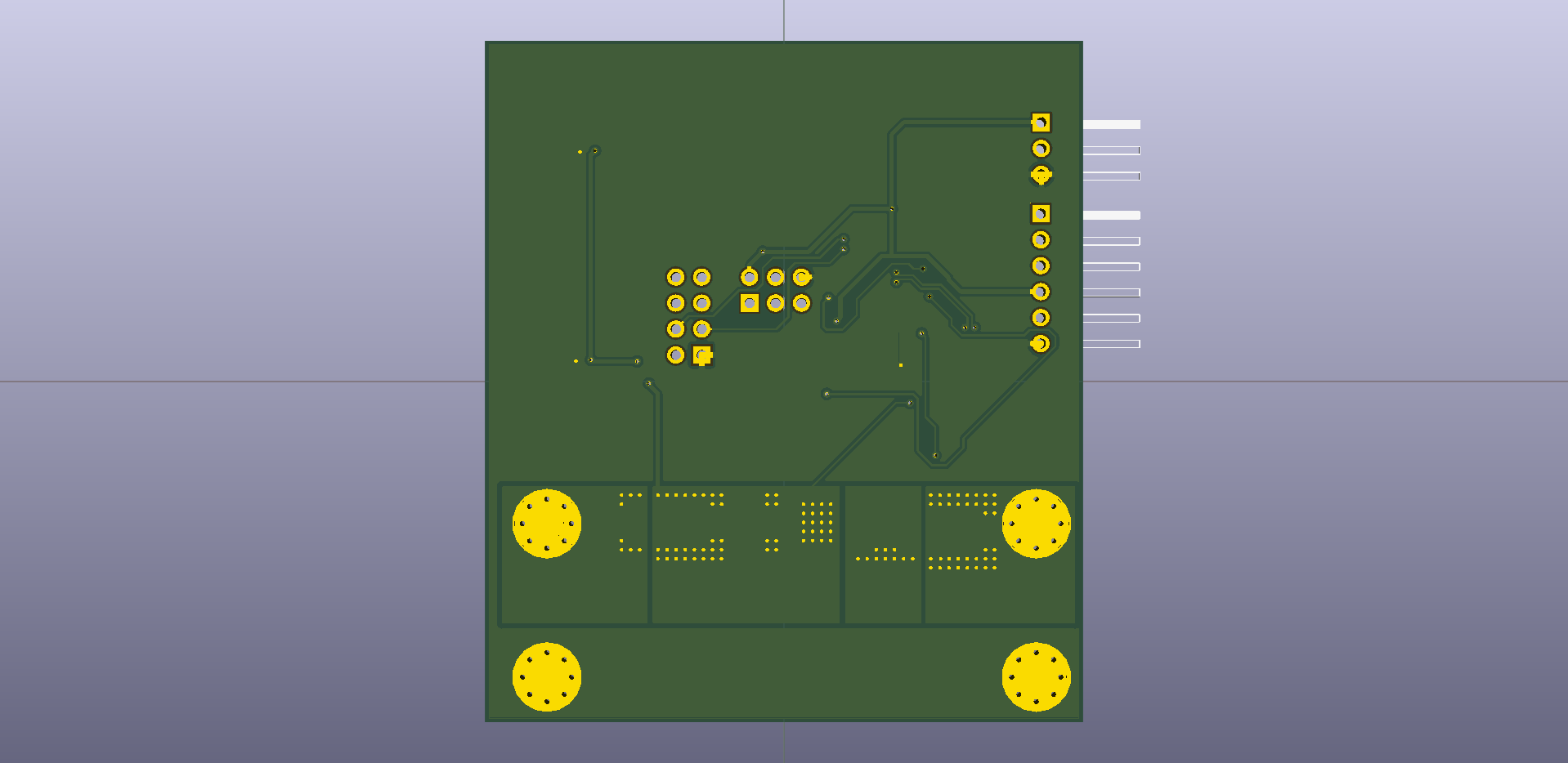
PWM10 is an open-source printed circuit board by Duckle29, from the Duckle29/PWM-Solar-Charge-Controller repository on GitHub, published under the MIT licence. It is a 2-layer board of 58.4 × 66.7 mm with 55 parts on 52 nets, routed with 629 tracks and 133 vias.
It is built around the ATMEGA328P-AU, LMR14006XDDC and ZXGD3009E6TA, with the PMEG6010AESBYL and WS2812 among its other parts. Its parts include 19 capacitors, 12 resistors, 8 connectors, 7 diodes and 4 ICs. It belongs with the AVR (ATmega, ATtiny) boards of this library.


I have decided to revive this project again. It's gonna be brought back as the PWM10, as It'll be designed to handle 10A, which is a little over a 140W panel. The Rev2 files are designed using KiCAD
This is an attempt at making an Arduino powered PWM solar charge controller.
The design of this controller is heavily based on Julian Iletts PWM5 controller, which he sadly discontinued. He however makes some interesting Youtube videos.
This is not done, and there is no protection added to the board as of yet. This first revision is simply as complete as I could make it, before my patience ran out for that day. I might very well add the last few bits and bops within a few days.
And as such, features and implementations of the hardware has yet to be decided.
This board is:
The following things need to be added:
If I decide the board is ready to go, I will order some assembled boards. If people are interested in some assembled boards, then comment in the issue that I opened for that purpose. I might order some home and send them to you for the price it cost me, and nothing more (that's assembled board cost + shipping)
 Greetings!
| Qty | Value | Footprint | References |
|---|---|---|---|
| 6 | 100nF | Capacitors_SMD:C_0805_HandSoldering | C6, C7, C10, C11, C12, C13 |
| 3 | 15uF 10v | Capacitors_SMD:C_1206_HandSoldering | C14, C18, C19 |
| 3 | 1uF | Capacitors_SMD:C_0805_HandSoldering | C3, C4, C5 |
| 3 | D_Small | Diodes_SMD:D_SOD-123 | D1, D2, D3 |
| 2 | 10K | Resistors_SMD:R_0603_HandSoldering | R3, R8 |
| 2 | 150 | Resistors_SMD:R_0603_HandSoldering | R1, R2 |
| 2 | 18pF | Capacitors_SMD:C_0805_HandSoldering | C8, C9 |
| 2 | 2.2uF | Capacitors_SMD:C_0805_HandSoldering | C16, C17 |
| 2 | 20.1K 1% | Resistors_SMD:R_0603_HandSoldering | R5, R7 |
| 2 | 47nF | Capacitors_SMD:C_0805_HandSoldering | C1, C2 |
| 2 | 82.5K 1% | Resistors_SMD:R_0603_HandSoldering | R4, R6 |
| 2 | PMEG6010AESBYL | diodes:SOD-993 | D5, D6 |
| 2 | SBR10E45P5-7 | diodes:PowerDI5 | D4, D7 |
| 1 | 10.4K | Resistors_SMD:R_0603_HandSoldering | R10 |
| 1 | 10uH | Resistors_SMD:R_1210_HandSoldering | L1 |
| 1 | 16MHz | Crystals:Crystal_SMD_HC49-SD | Y1 |
| 1 | 22uH | Resistors_SMD:R_1210_HandSoldering | L3 |
| 1 | 28K | Resistors_SMD:R_0603_HandSoldering | R11 |
| 1 | 33uF 5v | Capacitors_SMD:C_1206_HandSoldering | C15 |
| 1 | 47uH | Resistors_SMD:R_1210_HandSoldering | L2 |
| 1 | 57.6K | Resistors_SMD:R_0603_HandSoldering | R9 |
| 1 | 8.45K | Resistors_SMD:R_0603_HandSoldering | R12 |
| 1 | ATMEGA328P-A | Housings_QFP:TQFP-32_7x7mm_Pitch0.8mm | U4 |
| 1 | Bat+ | Mounting_Holes:MountingHole_3.2mm_M3_Pad_Via | P7 |
| 1 | Bat- | Mounting_Holes:MountingHole_3.2mm_M3_Pad_Via | P8 |
| 1 | CONN_01X06 | Pin_Headers:Pin_Header_Angled_1x06_Pitch2.54mm | P2 |
| 1 | CONN_02X03 | Pin_Headers:Pin_Header_Straight_2x03_Pitch2.54mm | P1 |
| 1 | CONN_02X04 | Pin_Headers:Pin_Header_Straight_2x04_Pitch2.54mm | P3 |
| 1 | LMR14006X | TO_SOT_Packages_SMD:TSOT-23-6_MK06A_HandSoldering | U3 |
| 1 | LMR14006Y | TO_SOT_Packages_SMD:TSOT-23-6_MK06A_HandSoldering | U2 |
| 1 | NTMFS4C10NT1G | Transistors:PG-TDSON-8 | Q1 |
| 1 | Panel+ | Mounting_Holes:MountingHole_3.2mm_M3_Pad_Via | P5 |
| 1 | Panel- | Mounting_Holes:MountingHole_3.2mm_M3_Pad_Via | P6 |
| 1 | WS2812 | Pin_Headers:Pin_Header_Angled_1x03_Pitch2.54mm | P4 |
| 1 | ZXGD3009E6 | TO_SOT_Packages_SMD:SOT-363_SC-70-6_Handsoldering | U1 |


eChook/eChook-Nano-PCB
Designspark Schematics and PCB files, and PCB Gerber Files

kitspace-forks/growbox-open-motion-mobo
A general purpose open source Arduino DUE based motion controller designed to run the Synthetos G2 motion control fimware


ssbingo/asksin-analyzer-rpi
Homematic/BidCoS-Funkanalyzer auf Raspberry-Pi-Basis: eigene Empfängerplatine, Node.js-Auswertung, Handbuch
It measures 58.4 × 66.7 mm and has 2 copper layers, 1.6 mm thick.
55 parts, built around the ATMEGA328P-AU, LMR14006XDDC, ZXGD3009E6TA and PMEG6010AESBYL. The full list of its parts is on this page, with links to each part's symbol and footprint where PCBKit's library has them.
From the Duckle29/PWM-Solar-Charge-Controller repository on GitHub, at the commit this page was made from: the board is hardware/Rev2/PWM10.kicad_pcb. PCBKit opens the board in the browser, with nothing to install.
Its repository publishes it under the MIT licence: you may reuse it on that licence's terms (keep the author's notice, and for a copyleft licence share your changes alike).