2 layers87 × 68 mm
 Domochip/WTeleInfo22
Un D1 Mini et quelques composants pour envoyer votre Téléinfo (Compteur EDF) sur votre Domotique
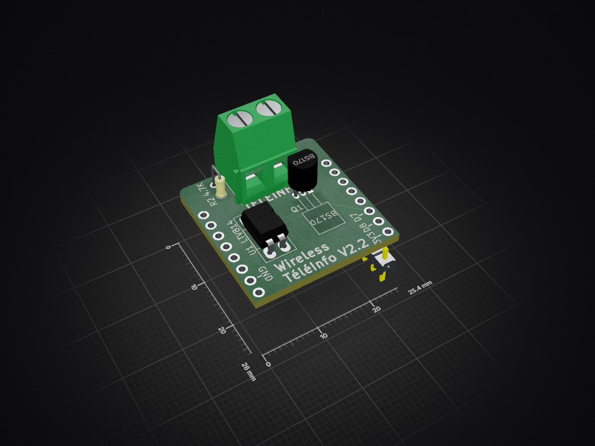
WirelessTeleInfo is an open-source printed circuit board by Domochip, from the Domochip/WTeleInfo repository on GitHub. It is a 2-layer board of 25.4 × 26 mm with 9 parts on 9 nets, routed with 56 tracks and 0 vias.
It is built around the LTV-814 and BS170. Its parts include 4 resistors, 2 ICs, 1 capacitor, 1 transistor and 1 connector. It belongs with the home automation and IoT boards and the ESP8266 boards of this library.


Ce projet utilise un D1 mini et quelques composants pour faire remonter les compteurs EDF à votre domotique.
Tous les fichiers necessaires sont dans le sous-dossier schematic et ont été conçu avec KiCAD.

Spécial Linky : Il faut remplacer R2 par une 1.5K et C3 n'est pas necessaire


Le projet du boitier (Fusion 360) se trouve dans le dossier box
(Ainsi que les fichiers STL à imprimer directement)

Le firmware Tasmota-téléinfo est utilisé pour animer le D1Mini
Vous pouvez le flasher directement depuis la page web "Install tasmota"
https://tasmota.github.io/install/

Vous devez appliquer ce Template :
{"NAME":"WTeleInfo","GPIO":[0,0,0,0,0,0,0,0,0,5152,0,0,0,0],"FLAG":0,"BASE":18,"CMND":"Module 0|TelePeriod 60"}
Commande à executer, si vous possedez un compteur Linky en Mode Standard (nouveau protocole):
EnergyConfig Standard
Pour plus de détails, veuillez vous référer à la documentation officielle :
https://tasmota.github.io/docs/Teleinfo/
| Qty | Value | Footprint | References |
|---|---|---|---|
| 2 | 10K | Resistors_SMD:R_0805_HandSoldering | R1, R3 |
| 1 | 100k | Resistors_SMD:R_0805_HandSoldering | R4 |
| 1 | 3.3nF | Capacitors_SMD:C_0805_HandSoldering | C3 |
| 1 | 4.7K | Resistors_ThroughHole:R_Axial_DIN0204_L3.6mm_D1.6mm_P2.54mm_Vertical | R2 |
| 1 | BS170 | TO_SOT_Packages_THT:TO-92_Horizontal2_Inline_Narrow_Oval | Q1 |
| 1 | LTV-814 | Housings_DIP:DIP-4_W7.62mm_Socket_LongPads | U1 |
| 1 | TeleInfo | Terminal_Blocks:TerminalBlock_bornier-2_P5.08mm | P2 |
| 1 | WeMos_mini | wemos_d1_mini:wemos-d1-mini-DIL-only | U2 |

Miceuz/triac-bloc
An universal power block based on triac. In essence this is a solid state relay with some bells and whistles

MayaPosch/DebounceHat
Fully isolated, input debounce Hat for Raspberry Pi, for up to 6 switches, relays and powered devices

tdouez/TeleinfoMySensors
Interface Téléinfo pour compteur Linky avec MySensors

synfinatic/GoProControl
GoPro WiFi controller board using an ESP8266 allowing easy integration with other circuits

markus-k/led-controller-hardware
KiCAD schematics and design files for my LED controller.


tdouez/Linky_TEMPO
Module de récupération des sorties relais pour le compteur Linky avec un contrat TEMPO Compatible en TIC historique et standard
It measures 25.4 × 26 mm and has 2 copper layers, 1.6 mm thick.
9 parts, built around the LTV-814 and BS170. The full list of its parts is on this page, with links to each part's symbol and footprint where PCBKit's library has them.
From the Domochip/WTeleInfo repository on GitHub, at the commit this page was made from: the board is schematic/WirelessTeleInfo.kicad_pcb and its schematic schematic/WirelessTeleInfo.kicad_sch. PCBKit opens the board in the browser, with nothing to install.
Its repository states no licence, so its author keeps all rights: ask Domochip before reusing the design.