

2 layers137.2 × 137.2 mm

 DerHobbyEntwickler/i-meic
The i-meic is a modular, expandable single-board computer based on the Intel 8088 CPU.
I meic pico V6 is an open-source printed circuit board by DerHobbyEntwickler, from the DerHobbyEntwickler/i-meic repository on GitHub, published under the GPL-3.0 licence. It is a 2-layer board of 100 × 100 mm with 60 parts on 121 nets, routed with 1,951 tracks and 37 vias.
It is built around the 74HC373D and AS6C4008-55PCN. Its parts include 15 capacitors, 12 diodes, 11 ICs, 10 resistors and 1 connector. It belongs with the computers and single-board computers boards and the RP2040 and AVR (ATmega, ATtiny) boards of this library.
(German version: README_de.md)
The i-meic is a modular, expandable single-board computer based on the Intel 8088 CPU.
The hardware aims to recreate an IBM PC using the simplest possible means. The PC compute core consists of the 8088 CPU and 1 MB of main memory. All input/output is handled by a Raspberry Pi RP2040 Pro Micro. That is faster, simpler and cheaper than classic peripheral chips.
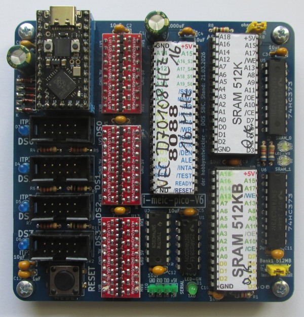
The name is derived from the German description of the project:
| Letter | Meaning |
|---|---|
| i | (i)ntel 8088 |
| m | (m)odular |
| e | (e)xpandable |
| i | s(i)ngle-board |
| c | (c)omputer |
Classic 8088 systems require a large number of peripheral chips (clock generator, bus drivers, interrupt controller, DMA, floppy/HDD controller, video, keyboard, etc.). The i-meic replaces this entire set of peripherals with a single microcontroller: the Raspberry Pi Pico.
The PC compute core consists of:
The Raspberry Pi RP2040 Pro Micro (ARM Cortex-M0+) takes care of:
This architecture is unusually powerful because the Pico runs at a significantly higher clock frequency than the historic 8088 peripherals and can therefore handle I/O operations very quickly.
This is how a runnable DOS computer is created from source code:
   ┌────────────────────────────────────────────────────────────────┐
   │  70_RON-BIOS-NASM …  BIOS.ASM  (8088 assembler, NASM)          │
   │        │  nasm -f bin                                          │
   │        ▼                                                       │
   │     BIOS.BIN  (pure 8088 binary BIOS, segment F800:0000)       │
   │        │  COM2INC  (see 60_FPC_Lazarus/25_LAZ_CLI64_COM2INC)   │
   │        ▼                                                       │
   │     BIOS.INC  (Pascal byte array  BIOS_ARR[…])                 │
   └────────┬───────────────────────────────────────────────────────┘
            │  gets embedded into the Pico firmware
            ▼
   ┌────────────────────────────────────────────────────────────────┐
   │  10_…/20_Lazarus_PICO…  Firmware (Free Pascal / RP2040)        │
   │        │  Lazarus / FPC                                        │
   │        ▼                                                       │
   │     imeic_dos.uf2   →   flash onto the Raspberry Pi Pico       │
   └────────┬───────────────────────────────────────────────────────┘
            │  Pico boots:
            │  1. loads BIOS_ARR into SRAM (F800:0000)
            │  2. clocks the 8088 CPU
            │  3. services all I/O requests (IORQ)
            ▼
   ┌────────────────────────────────────────────────────────────────┐
│ i-meic board (8088 + 2×512 KB SRAM) ←── serial ───┐ │| Folder | Contents |
|---|---|
10_i-meic-pico_V6/ | The actual i-meic board: KiCAD hardware and Pico firmware (ARM cross-compiler, I/O interface for DOS) |
10_i-meic-pico_V6/10_KiCAD/ | KiCAD project, schematic, layout, Gerber data for PCB manufacturing |
10_i-meic-pico_V6/20_Lazarus_PICO_i-meic-pico_V6_DOS/ | Source code of the Pico firmware for the ARM cross-compiler (Free Pascal / Lazarus). The I/O interface here is designed for DOS. |
60_FPC_Lazarus/ | Host PC tools (Free Pascal / Lazarus) for Windows & Linux |
60_FPC_Lazarus/20_LAZ_Console64_GUI64_Win64_Linux/ | CONSOLE64 – terminal/console program for all i-meic (central tool) |
60_FPC_Lazarus/25_LAZ_CLI64_COM2INC/ | COM2INC – command-line tool that converts a binary file into a Pascal/NASM include (byte array) |
70_RON-BIOS-NASM_i-meic_WIN_Linux/ | RON-BIOS – the 8088 BIOS in NASM assembler including build scripts |
Operating-system variants of the firmware: For the i-meic board there are several firmware variants that differ only in the I/O interface – currently DOS (
…_DOS) and CP/M-86 (…_CPM86). The hardware and the ARM cross-compiler are identical in each case.
The ready-to-use Gerber data is located at
10_i-meic-pico_V6/10_KiCAD/gerber_i-meic-pico_V6.zip and can be uploaded
directly to a PCB manufacturer. The schematic and layout for further
development are in the same folder as a KiCAD project.
Copy imeic_dos.uf2 onto the Raspberry Pi Pico (BOOTSEL mode).
Start CONSOLE64 (in the folder
60_FPC_Lazarus/20_LAZ_Console64_GUI64_Win64_Linux/bin/), set the correct
COM port and 921600 baud, then power up the i-meic.
units/
folder, adapted for this project – see the warning below), original:
https://github.com/michael-ring/pico-fpcexamplesunits/ folder have been modified and
adapted for this project and must not be replaced by the current
upstream version (otherwise compilation errors will occur).LICENSE_NASM.TXT).This project is licensed under the GNU General Public License v3.0 – see
LICENSE. The BIOS and COM2INC additionally include the NASM
license (LICENSE_NASM.TXT) for the bundled NASM binaries.
| Qty | Value | Footprint | References |
|---|---|---|---|
| 13 | 1uF | board-library:C_Disc_D5.0mm_W2.5mm_P5.00mm_2 | C2, C3, C4, C5, C6, C7, C8, C9, C10, C11, C12, C13, C18 |
| 5 | 1N4001 | board-library:Diode_1N4001 | D7, D8, D9, D10, D11 |
| 4 | board-library:Bohrung_M3_mit_GND | MH1, MH2, MH3, MH4 | |
| 4 | 2K2 | Resistor_THT:R_Axial_DIN0204_L3.6mm_D1.6mm_P7.62mm_Horizontal | R4, R5, R6, R7 |
| 4 | Stecker_ITP3_02x05 | board-library:Stecker_ITP3_2x05_RM_2.54mm_Vertical | J_DS0, J_DS1, J_DS2, J_DS3 |
| 3 | 10K | Resistor_THT:R_Axial_DIN0204_L3.6mm_D1.6mm_P7.62mm_Horizontal | R8, R9, R11 |
| 3 | Logic_Level_Converter_8_BIT_BiDirectional_Module_5V_to_3.3V | board-library:Logic_Level_Converter_8Bit_BiDirectional_Module_5V_to_3.3V | U3, U10, U13 |
| 2 | 470uF | board-library:CP_470uF_Radial_D8.0mm_P3.50mm | C1, C14 |
| 2 | 6K8 | Resistor_THT:R_Axial_DIN0204_L3.6mm_D1.6mm_P7.62mm_Horizontal | R2, R15 |
| 2 | 74HC373 | Package_DIP:DIP-20_W7.62mm | U5, U6 |
| 2 | AS6C4008-55PCN | Package_DIP:DIP-32_W15.24mm | U7, U8 |
| 1 | 1K | Resistor_THT:R_Axial_DIN0204_L3.6mm_D1.6mm_P7.62mm_Horizontal | R1 |
| 1 | 7400 | Package_DIP:DIP-14_W7.62mm | U1 |
| 1 | 7402 | Package_DIP:DIP-14_W7.62mm | U2 |
| 1 | 8088 | Package_DIP:DIP-40_W15.24mm | U4 |
| 1 | Conn_128K_512K | Connector_PinHeader_2.54mm:PinHeader_1x02_P2.54mm_Vertical | JP2 |
| 1 | Conn_SRAM_inst | Connector_PinHeader_2.54mm:PinHeader_1x03_P2.54mm_Vertical | JP1 |
| 1 | Conn_UART0 | Connector_PinHeader_2.54mm:PinHeader_1x04_P2.54mm_Vertical | J10 |
| 1 | LED_BL_DS0 | LED_THT:LED_D3.0mm | D3 |
| 1 | LED_BL_DS1 | LED_THT:LED_D3.0mm | D4 |
| 1 | LED_BL_DS2 | LED_THT:LED_D3.0mm | D5 |
| 1 | LED_BL_DS3 | LED_THT:LED_D3.0mm | D6 |
| 1 | LED_GN_UART0 | LED_THT:LED_D3.0mm | D1 |
| 1 | LED_WS_SRAM0 | LED_THT:LED_D3.0mm | D17 |
| 1 | LED_WS_SRAM1 | LED_THT:LED_D3.0mm | D2 |
| 1 | RP2040_ProMicro_Modul_nach_PORTs | board-library:RP2040_ProMicro_Modul | U12 |
| 1 | Taster_RESET | board-library:Schalter_Taster_PUSH-12,55mm_und_6,5mm | SW2 |

SmallRobot2000/AMIX-68k
Motorola 68010 based sbc with IDE, keyboard, DMA, PIT, Xosera & more!

Redherring32/OpenTendo
An Open-Source HardWare (OSHW) recreation of the original 1985 front-loading NES Motherboard


Redherring32/OpenTendo-TopLoader
An Open Source HardWare (OSHW) recreation of the 1993 toploading NES motherboard (Also known as NES-101)

RWeick/Gameboy-Color-Megamem-Card
All data necessary to produce a Mega Memory Card for the Gameboy Color

inmbolmie/elfacun
Hardware project to create a chess module compatible with the old Mephisto modular boards (Exclusive, Modular, München) that will provide connectivity to a wide variety of chess apps and services

mggates39/68hc11_SBC
Building a Single Board Computer around the MC68HC11. It will include my first attempt with KiCad designing a PCB
It measures 100 × 100 mm and has 2 copper layers, 1.6 mm thick.
60 parts, built around the 74HC373D and AS6C4008-55PCN. The full list of its parts is on this page, with links to each part's symbol and footprint where PCBKit's library has them.
From the DerHobbyEntwickler/i-meic repository on GitHub, at the commit this page was made from: the board is 10_i-meic-pico_V6/10_KiCAD/i-meic-pico_V6/i-meic-pico_V6.kicad_pcb and its schematic 10_i-meic-pico_V6/10_KiCAD/i-meic-pico_V6/i-meic-pico_V6.kicad_sch. PCBKit opens the board in the browser, with nothing to install.
Its repository publishes it under the GPL-3.0 licence: you may reuse it on that licence's terms (keep the author's notice, and for a copyleft licence share your changes alike).