4 layers60 × 56 mm
STM32F4 Breakout REV2
alphaseneca/pcb_design_repo
A repository for storing and documenting the pcb design files.
63 parts1MIT

 DallasFormulaRacing/PneumaticPaddleShifting
An embedded system for the driver to perform up and down shifts with pneumatic paddle shifters.
STM32F4 Breakout is an open-source printed circuit board by DallasFormulaRacing, from the DallasFormulaRacing/PneumaticPaddleShifting repository on GitHub. It is a 4-layer board of 156.6 × 143.1 mm with 56 parts on 90 nets, routed with 528 tracks and 122 vias.
It is built around the STM32F405RGT6, TJA1051T and MP2303ADN, with the USBLC6-2SC6 and AO3401A among its other parts. Its parts include 16 capacitors, 13 resistors, 7 connectors, 5 ICs and 4 diodes. It belongs with the interfaces and adapters boards and the STM32 boards of this library.


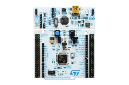
The STM32 Nucleo F466RE microcontroller development board is used as the current target device for code merged to the main and develop branches. Theoretically, other Arm Cortex M4 based STM32 devices with the necessary peripherals should be able to run the same program.
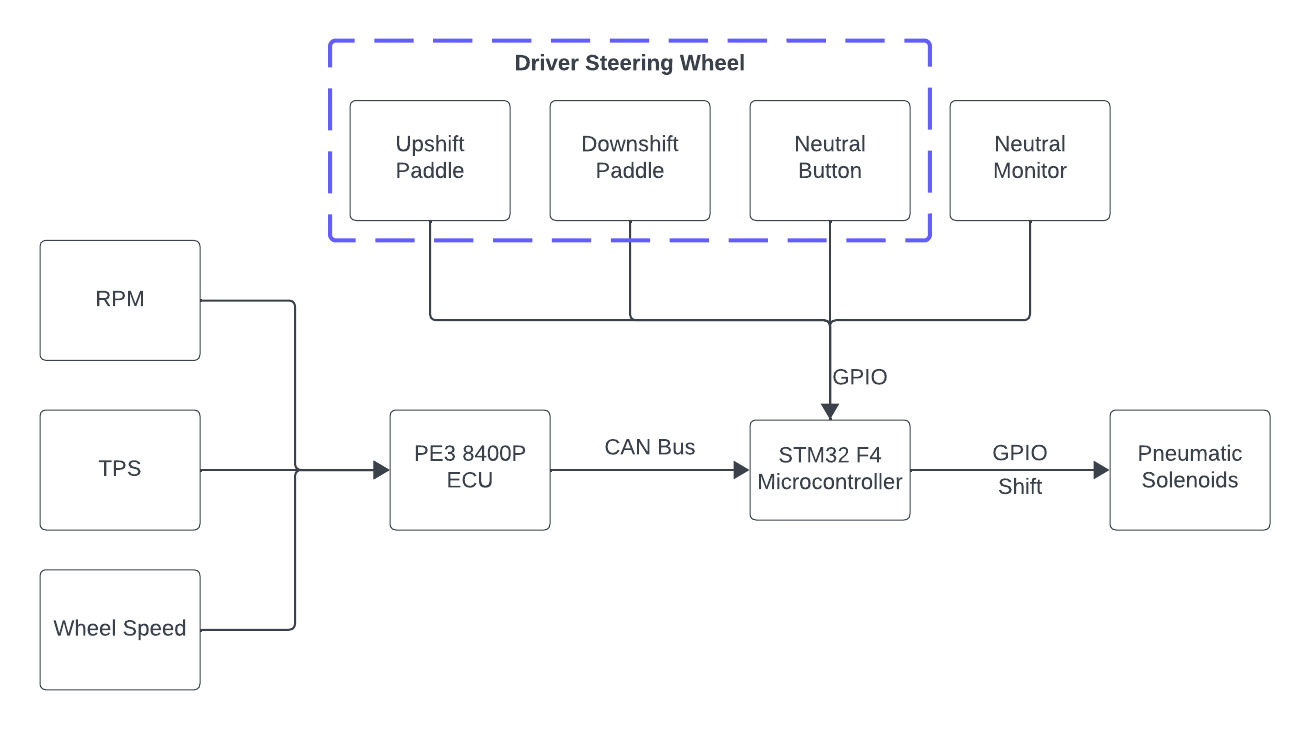
arm-none-eabi toolchain.Shifter_System/Tests.High level system diagram:
Firmware design:
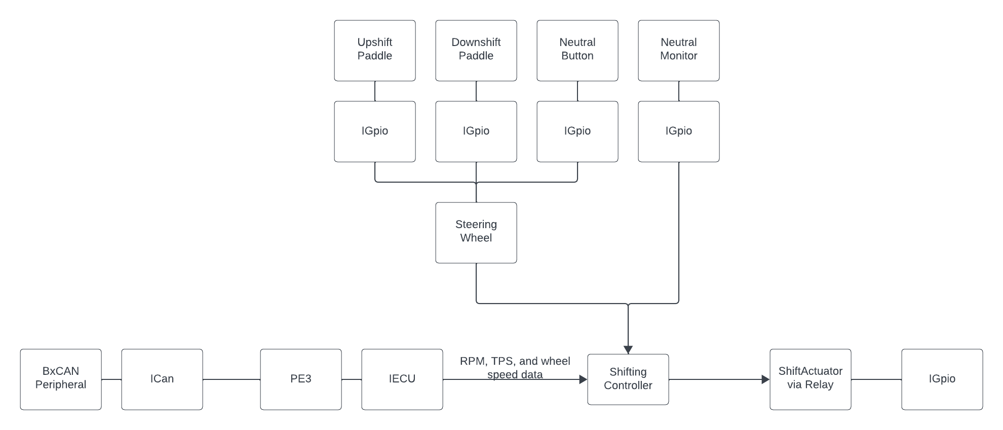
It is assumed that the user inputs are simple GPIO signals (i.e., high and low voltages). The upshift and downshift paddle will request their respective shift. The neutral button is for the user to set the car into neutral, and this may be verified with a neutral “monitor”. The neutral monitor is to act as some sort of sensor or switch.
Do note, however, that these inputs have not yet been tested. It is currently unknown whether they will require any signal “debouncing” so that the behavior is not jittery or sporadic. It has also been highly recommended to consider more fail-safe mechanisms for the scenario that the user input begins to malfunction.
The device reads RPM, TPS, and wheel speeds from the PE3 8400-P ECU. This ECU implementation library was adopted from the race team’s previous efforts in other projects.
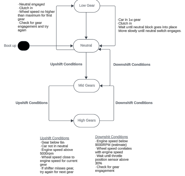
The Shift Controller is a high-level component responsible for evaluating the driver’s shift requests. It depends on an ECU and several GPIO components to be used. Internally, a state machine is used to perform different behaviors. This approach offers the following advantages: dramatically simplifies the logic, increases performance, isolated behavior, and transition actions. The performance is increased as it only performs the conditional checks that are unique to each state. Due to the isolated behaviors, we can also easily determine and rigorously test every edge case for every state.
You may see the design of the state machine below in Figure 9. In practice, there are 6 gears. However, gears 2 through 5 had the same logic and state transition conditions, so they were condensed into a single state. So, the nomenclature was established as the following: Low Gear refers to first gear, Mid Gears refers to second to fifth gear, and High Gear refers to sixth gear.
One important design choice is how we intended to manage the transition to/from the neutral state. In practice, to go from first to second gear, the driver typically needs to go through neutral. Although an “immediate pass-through" transition was considered, the team ultimately decided to require the driver to manually transition through neutral. This user experience will be in reminiscence of a typical vehicle to offer a more seamless and practical learning curve to use.
It is worth mentioning that, due to time constraints in the development of the Shift Actuation, the Shift Controller is incomplete in respect to commanding for a shift.
ShiftController state machine:
It is assumed that the required hardware interface for the shift actuator would be a GPIO (i.e., high and low) signal. However, due to time constraints, requirements of the hardware interface were not tested and verified for modifications.
| Qty | Value | Footprint | References |
|---|---|---|---|
| 5 | 100n | Capacitor_SMD:C_0402_1005Metric | C4, C5, C6, C7, C8 |
| 4 | MountingHole_Pad | MountingHole:MountingHole_4.3mm_M4_Pad_Via | H1, H2, H3, H4 |
| 3 | 10u | Capacitor_SMD:C_1206_3216Metric | C13, C15, C16 |
| 2 | 120 | Resistor_SMD:R_0603_1608Metric_Pad0.98x0.95mm_HandSolder | R12, R13 |
| 2 | 12p | Capacitor_SMD:C_0402_1005Metric | C11, C12 |
| 2 | 2k2 | Resistor_SMD:R_0402_1005Metric | R9, R10 |
| 2 | 2u2 | Capacitor_SMD:C_0603_1608Metric | C1, C2 |
| 2 | B5189W | Diode_SMD:D_SOD-123 | D2, D3 |
| 2 | Conn_01x04 | Connector_Molex:Molex_PicoBlade_53048-0410_1x04_P1.25mm_Horizontal | J3, J4 |
| 2 | TJA1051T | Package_SO:SOIC-8_3.9x4.9mm_P1.27mm | U4, U5 |
| 1 | 100k | Resistor_SMD:R_0603_1608Metric | R4 |
| 1 | 10k | Resistor_SMD:R_0402_1005Metric | R1 |
| 1 | 10n | Capacitor_SMD:C_0402_1005Metric | C10 |
| 1 | 10n | Capacitor_SMD:C_0603_1608Metric | C14 |
| 1 | 10u | Inductor_SMD:L_Sunlord_MWSA0518S | L2 |
| 1 | 15k | Resistor_SMD:R_0603_1608Metric | R7 |
| 1 | 16MHz | Crystal:Crystal_SMD_3225-4Pin_3.2x2.5mm | Y1 |
| 1 | 1k | Resistor_SMD:R_0603_1608Metric | R11 |
| 1 | 1k5 | Resistor_SMD:R_0603_1608Metric | R3 |
| 1 | 1u | Capacitor_SMD:C_0402_1005Metric | C9 |
| 1 | 250mA | Fuse:Fuse_1206_3216Metric | F1 |
| 1 | 270 | Resistor_SMD:R_0603_1608Metric | R8 |
| 1 | 39n | Inductor_SMD:L_0402_1005Metric | L1 |
| 1 | 47 | Resistor_SMD:R_0402_1005Metric | R2 |
| 1 | 47k | Resistor_SMD:R_0603_1608Metric | R6 |
| 1 | 4u7 | Capacitor_SMD:C_0603_1608Metric | C3 |
| 1 | 600 @ 600MHz | Inductor_SMD:L_0805_2012Metric | FB1 |
| 1 | 68k | Resistor_SMD:R_0603_1608Metric | R5 |
| 1 | AO3401A | Package_TO_SOT_SMD:SOT-23 | Q1 |
| 1 | CAN Connector1 | Connector_Molex:Molex_Mega-Fit_76829-0006_2x03_P5.70mm_Vertical | J8 |
| 1 | CAN Connector2 | Connector_Molex:Molex_Mega-Fit_76829-0006_2x03_P5.70mm_Vertical | J9 |
| 1 | LED_Small | LED_SMD:LED_0603_1608Metric | D1 |
| 1 | MP2303ADN | Package_SO:SOIC-8-1EP_3.9x4.9mm_P1.27mm_EP2.62x3.51mm | U2 |
| 1 | RED | LED_SMD:LED_0603_1608Metric | D4 |
| 1 | STM32F405RGT6 | Package_QFP:LQFP-64_10x10mm_P0.5mm | U1 |
| 1 | SWD | Connector_PinHeader_1.27mm:PinHeader_2x05_P1.27mm_Vertical_SMD | J2 |
| 1 | SW_SPDT | Button_Switch_SMD:SW_SPDT_PCM12 | SW1 |
| 1 | Screw_Terminal_01x02 | TerminalBlock_Phoenix:TerminalBlock_Phoenix_PT-1,5-2-3.5-H_1x02_P3.50mm_Horizontal | J1 |
| 1 | USBLC6-2SC6 | Package_TO_SOT_SMD:SOT-23-6 | U3 |
| 1 | USB_B | Connector_USB:USB_B_Lumberg_2411_02_Horizontal | J5 |
alphaseneca/pcb_design_repo
A repository for storing and documenting the pcb design files.

MILOUDIAS/Basic_STM32_Dev_Board
The Project is about an STM32 based development board used mainly for educative purposes and prototyping designed in Kicad 8

TilenTinta/ReflowOven_controller
An open source controller for converting kitchen toaster oven to reflow oven


amrithHN/stm32f4xx_minimal_dev
stm32f4 minimal dev board with few sensors

majdbiw4200/STM32F405RGT-dev-board
STM32 + USB + Buck Converter PCB Design

pravinsharma15k-ops/STM32F4-Test-Board
STM32F405-based test board designed in KiCad 10, with buck converter, USB, SWD, I2C and UART.

Codebreaker000/PCB_DESIGNS
Contains all PCB designs with Schematics and Board view file's and both pdf's to understand and gerber files and the view and layout of the PCB's.
It measures 156.6 × 143.1 mm and has 4 copper layers, 1.6 mm thick.
56 parts, built around the STM32F405RGT6, TJA1051T, MP2303ADN and USBLC6-2SC6. The full list of its parts is on this page, with links to each part's symbol and footprint where PCBKit's library has them.
From the DallasFormulaRacing/PneumaticPaddleShifting repository on GitHub, at the commit this page was made from: the board is Hardware/STM32F4/STM32F4_Breakout.kicad_pcb and its schematic Hardware/STM32F4/STM32F4_Breakout.kicad_sch. PCBKit opens the board in the browser, with nothing to install.
Its repository states no licence, so its author keeps all rights: ask DallasFormulaRacing before reusing the design.