2 layers40 × 20 mm
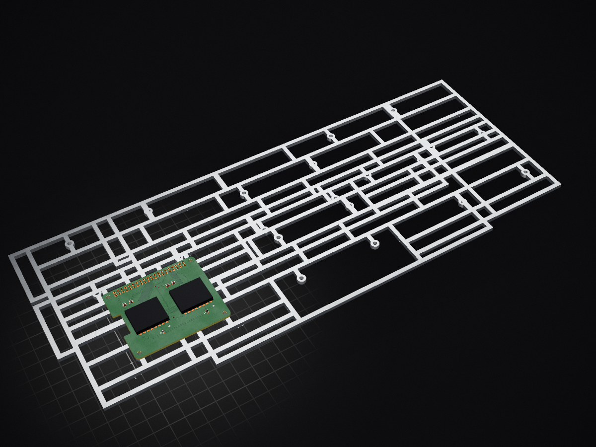
 DJ2RF/DoppelLoraModul-RaspberryPi-HAT1
Raspberry HAT for Nerdverlag LoRa Analyser or any other projects
DoppelLoraModulauf Raspi is an open-source printed circuit board by DJ2RF, from the DJ2RF/DoppelLoraModul-RaspberryPi-HAT repository on GitHub, published under the MIT licence. It is a 2-layer board of 65 × 56 mm with 13 parts on 35 nets, routed with 236 tracks and 16 vias.
Its parts include 4 capacitors, 2 resistors, 2 ICs and 1 connector. It belongs with the radio and wireless and sensors and measurement boards of this library.
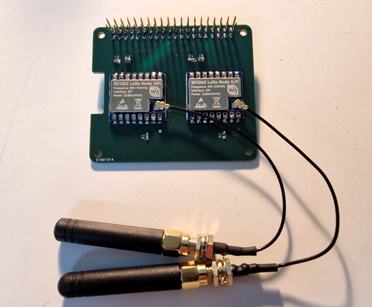
Raspberry HAT for Nerdverlag LoRa Analyser or any other projects
Dieses KiCad-Projekt enthält die Schaltung und das Leiterplattenlayout für ein Raspberry-Pi-HAT mit zwei unabhängigen LoRa-Funkmodulen auf Basis des Semtech SX1262.
Die Platine wurde für den gleichzeitigen Betrieb eines 433-MHz- und eines 863/868-MHz-Moduls entwickelt. Beide Funkmodule verwenden den gemeinsamen SPI0-Bus des Raspberry Pi, besitzen jedoch getrennte Chip-Select-, Reset-, Busy-, Interrupt- und HF-Umschaltleitungen.
Das HAT ist insbesondere für den Einsatz mit dem LoRa MeshRadio Analyzer und weiteren Raspberry-Pi-basierten LoRa-Empfangs- und Analyseprojekten vorgesehen.
Die Platine ist für folgende Waveshare-Core1262-Module ausgelegt:
Waveshare Core1262-LF
Waveshare Core1262-HF
Beide Module basieren auf dem SX1262 und besitzen dieselbe mechanische sowie elektrische Anschlussbelegung.
Beide SX1262-Module verwenden gemeinsam:
| Signal | Raspberry Pi GPIO | Physischer Pin |
|---|---|---|
| SPI0 MOSI | GPIO10 | Pin 19 |
| SPI0 MISO | GPIO9 | Pin 21 |
| SPI0 SCLK | GPIO11 | Pin 23 |
Die Module werden über getrennte Chip-Select-Leitungen angesprochen.
| Funktion | Raspberry Pi GPIO | Physischer Pin |
|---|---|---|
| Chip Select | GPIO8 / CE0 | Pin 24 |
| Reset | GPIO22 | Pin 15 |
| Busy | GPIO23 | Pin 16 |
| DIO1 | GPIO24 | Pin 18 |
| RXEN | GPIO25 | Pin 22 |
| TXEN | GPIO5 | Pin 29 |
Linux-Gerät:
/dev/spidev0.0 433-MHz-Modul Funktion Raspberry Pi GPIO Physischer Pin Chip Select GPIO7 / CE1 Pin 26 Reset GPIO17 Pin 11 Busy GPIO27 Pin 13 DIO1 GPIO18 Pin 12 RXEN GPIO6 Pin 31 TXEN GPIO13 Pin 33
Linux-Gerät:
/dev/spidev0.1 Funktionsprinzip
Die beiden LoRa-Module können unabhängig voneinander konfiguriert und gleichzeitig betrieben werden.
Typische Verwendung:
433-MHz-Modul für LoRa-Verbindungen im 70-cm-Bereich 863-/868-MHz-Modul für Sensoren, Telemetrie und ISM-LoRa-Anwendungen paralleler Empfang auf beiden Frequenzbereichen Einsatz als Funk-Frontend für den LoRa MeshRadio Analyzer Entwicklung eigener Raspberry-Pi-LoRa-Anwendungen
Die Antennen werden direkt an den U.FL-/IPEX-Anschlüssen der jeweiligen Core1262-Module angeschlossen.
HAT-ID-EEPROM
Inhalt des Repositorys
Das Repository enthält die wesentlichen KiCad-Projektdateien:
*.kicad_pro *.kicad_sch *.kicad_pcb fp-lib-table sym-lib-table Nerdverlag.pretty/
Eigene Symbole und Footprints werden zusammen mit dem Projekt gespeichert, damit der Schaltplan und das Leiterplattenlayout auch auf anderen Rechnern vollständig geöffnet werden können.
Automatisch erzeugte KiCad-Backups, Sperrdateien und persönliche Arbeitsplatzdateien werden nicht versioniert.
Voraussetzungen
Zum Bearbeiten des Projekts wird eine aktuelle KiCad-Version empfohlen.
Das Projekt wurde mit KiCad 10 erstellt.
Für den späteren Betrieb auf dem Raspberry Pi müssen SPI und die GPIO-Schnittstellen aktiviert sein.
Kontrolle unter Linux:
ls -l /dev/spidev0.0 /dev/spidev0.1 ls -l /dev/gpiochip*
Der verwendete Benutzer sollte Mitglied der Gruppen spi und gpio sein.
Projektstatus
Das Projekt befindet sich in aktiver Entwicklung.
Vor einer Fertigung sollten mindestens folgende Punkte geprüft werden:
KiCad ERC ohne relevante Fehler KiCad DRC ohne relevante Fehler korrekte Footprints und Padnummern ausreichende Leiterbahnbreiten für die Stromversorgung vollständig gefüllte GND-Flächen korrekte Bestückungsbezeichnungen für LF- und HF-Modul mechanische Abstände zum Raspberry Pi vollständige Gerber- und Bohrdatenausgabe
Eine Fertigung sollte immer auf Grundlage eines abschließend geprüften Versionsstands erfolgen.
Hinweis zum Funkbetrieb
Für den Funkbetrieb gelten die jeweils nationalen Vorschriften zu Frequenzbereichen, Sendeleistungen, Bandbreiten und zulässigen Anwendungen.
Der Betreiber ist selbst dafür verantwortlich, die gesetzlichen Bestimmungen und gegebenenfalls die für den Amateurfunk geltenden Regelungen einzuhalten.
Die Platine selbst stellt lediglich die technische Hardwareplattform bereit.
Lizenz und Nutzung
Dieses Projekt ist für eigene Entwicklungs-, Forschungs- und Ausbildungszwecke vorgesehen.
Eine kommerzielle Nutzung, Weitergabe oder Fertigung ist nur nach vorheriger Zustimmung des Rechteinhabers gestattet, sofern keine separate Lizenzdatei etwas anderes festlegt.
Friedrich Riedhammer – DJ2RF
Nerdverlag
You can get the Software LoRa Analyser for free
Email: fritz@nerdverlag.com
© 2026 Nerdverlag
Friedrich Riedhammer
All rights reserved.
This KiCad project contains the schematic and PCB layout for a Raspberry Pi HAT with two independent LoRa radio modules based on the Semtech SX1262.
The board was designed for the simultaneous operation of one 433 MHz module and one 863/868 MHz module. Both radio modules share the Raspberry Pi SPI0 bus, while using separate chip-select, reset, busy, interrupt, and RF switch control lines.
The HAT is primarily intended for use with the LoRa MeshRadio Analyzer and other Raspberry Pi-based LoRa receiver and analysis projects.
The board is designed for the following Waveshare Core1262 modules:
Waveshare Core1262-LF
Waveshare Core1262-HF
Both modules are based on the SX1262 and use the same mechanical and electrical pinout.
Both SX1262 modules share the following SPI signals:
| Signal | Raspberry Pi GPIO | Physical Pin |
|---|---|---|
| SPI0 MOSI | GPIO10 | Pin 19 |
| SPI0 MISO | GPIO9 | Pin 21 |
| SPI0 SCLK | GPIO11 | Pin 23 |
The modules are addressed using separate chip-select lines.
| Function | Raspberry Pi GPIO | Physical Pin |
|---|---|---|
| Chip Select | GPIO8 / CE0 | Pin 24 |
| Reset | GPIO22 | Pin 15 |
| Busy | GPIO23 | Pin 16 |
| DIO1 | GPIO24 | Pin 18 |
| RXEN | GPIO25 | Pin 22 |
| TXEN | GPIO5 | Pin 29 |
Linux device:
/dev/spidev0.0 433 MHz Module Function Raspberry Pi GPIO Physical Pin Chip Select GPIO7 / CE1 Pin 26 Reset GPIO17 Pin 11 Busy GPIO27 Pin 13 DIO1 GPIO18 Pin 12 RXEN GPIO6 Pin 31 TXEN GPIO13 Pin 33
Linux device:
/dev/spidev0.1 Operating Principle
The two LoRa modules can be configured independently and operated at the same time.
Typical applications include:
433 MHz LoRa communication in the 70 cm band 863/868 MHz sensor, telemetry, and ISM LoRa applications Simultaneous reception in both frequency ranges Use as a radio frontend for the LoRa MeshRadio Analyzer Development of custom Raspberry Pi LoRa applications
The antennas are connected directly to the U.FL/IPEX connectors on the respective Core1262 modules.
Repository Contents
The repository contains the essential KiCad project files:
*.kicad_pro *.kicad_sch *.kicad_pcb fp-lib-table sym-lib-table Nerdverlag.pretty/
Custom symbols and footprints are stored together with the project so that the schematic and PCB layout can also be opened completely on another computer.
Automatically generated KiCad backups, lock files, and personal workspace files are not included in version control.
Requirements
A current version of KiCad is recommended for editing the project.
The project was created with KiCad 10.
For operation on a Raspberry Pi, SPI and the GPIO interfaces must be enabled.
Check the available devices under Linux:
ls -l /dev/spidev0.0 /dev/spidev0.1 ls -l /dev/gpiochip*
The user running the software should be a member of the spi and gpio groups.
Project Status
This project is under active development.
Before manufacturing the board, at least the following points should be checked:
KiCad ERC completed without relevant errors KiCad DRC completed without relevant errors Correct footprints and pad numbering Sufficient track widths for the power supply Completely filled GND planes Correct component designations for the LF and HF modules Mechanical clearance to the Raspberry Pi Complete Gerber and drill file output
Manufacturing should always be based on a final, fully verified version of the project.
Radio Operation Notice
Radio operation is subject to the applicable national regulations concerning frequency ranges, transmission power, bandwidth, duty cycle, and permitted applications.
The operator is responsible for complying with all applicable legal requirements and, where relevant, amateur radio regulations.
The board itself only provides the technical hardware platform.
License and Use
This project is intended for personal development, research, and educational purposes.
Commercial use, redistribution, or manufacturing requires prior permission from the copyright holder unless a separate license file explicitly permits such use.
Friedrich Riedhammer – DJ2RF
Nerdverlag
You can get the Software LoRa Analyser for free
Email: fritz@nerdverlag.com
© 2026 Nerdverlag
Friedrich Riedhammer
All rights reserved.
| Qty | Value | Footprint | References |
|---|---|---|---|
| 4 | C | Capacitor_SMD:C_0805_2012Metric | C2, C3, C4, C5 |
| 4 | MountingHole_2.7mm_M2.5 | MountingHole:MountingHole_2.7mm_M2.5 | MH1, MH2, MH3, MH4 |
| 2 | 10k | Resistor_SMD:R_0805_2012Metric | R1, R2 |
| 2 | ~ | Nerdverlag:Waveshare_Core1262_HF_LF | U3, U4 |
| 1 | Conn_02x20_Odd_Even | Connector_PinSocket_2.54mm:PinSocket_2x20_P2.54mm_Vertical | J1 |


samyk/magspoof
A portable device that can spoof/emulate any magnetic stripe, credit card or hotel card "wirelessly", even on standard magstripe (non-NFC/RFID) readers.

fossasia/pslab-scripts
Pocket Science Lab - Scripts for Sensor Experiments


willem-pennings/balancing-cube
A cube that balances itself in a corner or edge using reaction wheels

VoronDesign/Voron-Hardware
Cool Hardware designed by the Voron Design group

hoglet67/RGBtoHDMI
Bare-metal Raspberry Pi project that provides pixel-perfect sampling of Retro Computer RGB/YUV video and conversion to HDMI
It measures 65 × 56 mm and has 2 copper layers, 1.6 mm thick.
13 parts. The full list of its parts is on this page, with links to each part's symbol and footprint where PCBKit's library has them.
From the DJ2RF/DoppelLoraModul-RaspberryPi-HAT repository on GitHub, at the commit this page was made from: the board is DoppelLoraModulauf Raspi.kicad_pcb and its schematic DoppelLoraModulauf Raspi.kicad_sch. PCBKit opens the board in the browser, with nothing to install.
Its repository publishes it under the MIT licence: you may reuse it on that licence's terms (keep the author's notice, and for a copyleft licence share your changes alike).