2 layers53.3 × 31.8 mm
Constant current driver LM3404
DIaLOGIKa-GmbH/pcb_constant-current-driver
Testing PCBs for different constant current driver ICs
19 parts3MIT

 DIaLOGIKa-GmbH/pcb_constant-current-driver3
Testing PCBs for different constant current driver ICs
Constant current driver AL8860 is an open-source printed circuit board by DIaLOGIKa-GmbH, from the DIaLOGIKa-GmbH/pcb_constant-current-driver repository on GitHub, published under the MIT licence. It is a 2-layer board of 53.3 × 31.8 mm with 22 parts on 11 nets, routed with 28 tracks and 0 vias.
It is built around the AL8860WT, MMBT5551 and SS210. Its parts include 5 capacitors, 5 resistors, 3 connectors, 2 transistors and 1 IC.


This project is part of LibroDuct. We decided to publish some results of our LED driver designs to support the opensource maker scene. Feel free to use those results in your designs.
All those designs were tested with 9 IR-LEDs in series. These had a forward voltage of 14.0V.
The LM3404 and LM3404HV devices are monolithic switching regulators designed to deliver constant currents to high power LEDs. Ideal for automotive, industrial, and general lighting applications, these devices contain a high-side N-channel MOSFET switch with a current limit of 1.5A (typical) for step-down (Buck) regulators. Hysteretic controlled on-time and an external resistor allow the converter output voltage to adjust as needed to deliver a constant current to series and series-parallel connected LED arrays of varying number and type.
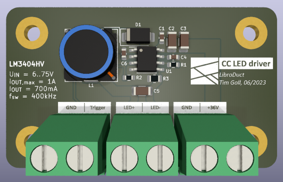 (LM3404 testing PCB render)
The layout of the PCB closely resembles the recommended design shown in the datasheet.
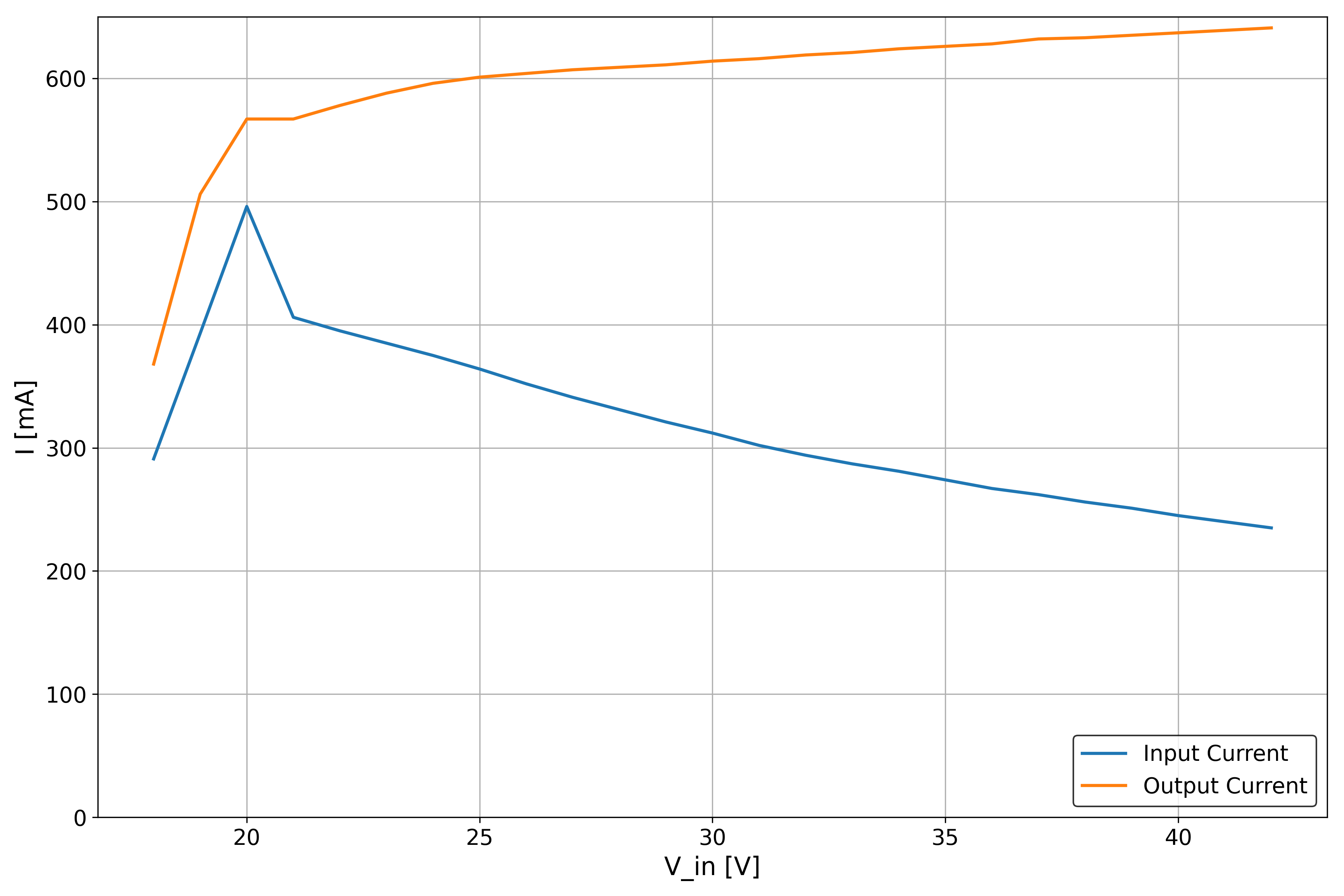 (LM3404 input and output current)
As can be seen in this plot, the output current is not that stable when the input voltage is changed. This makes the chip unusable for applications with a varying input voltage.
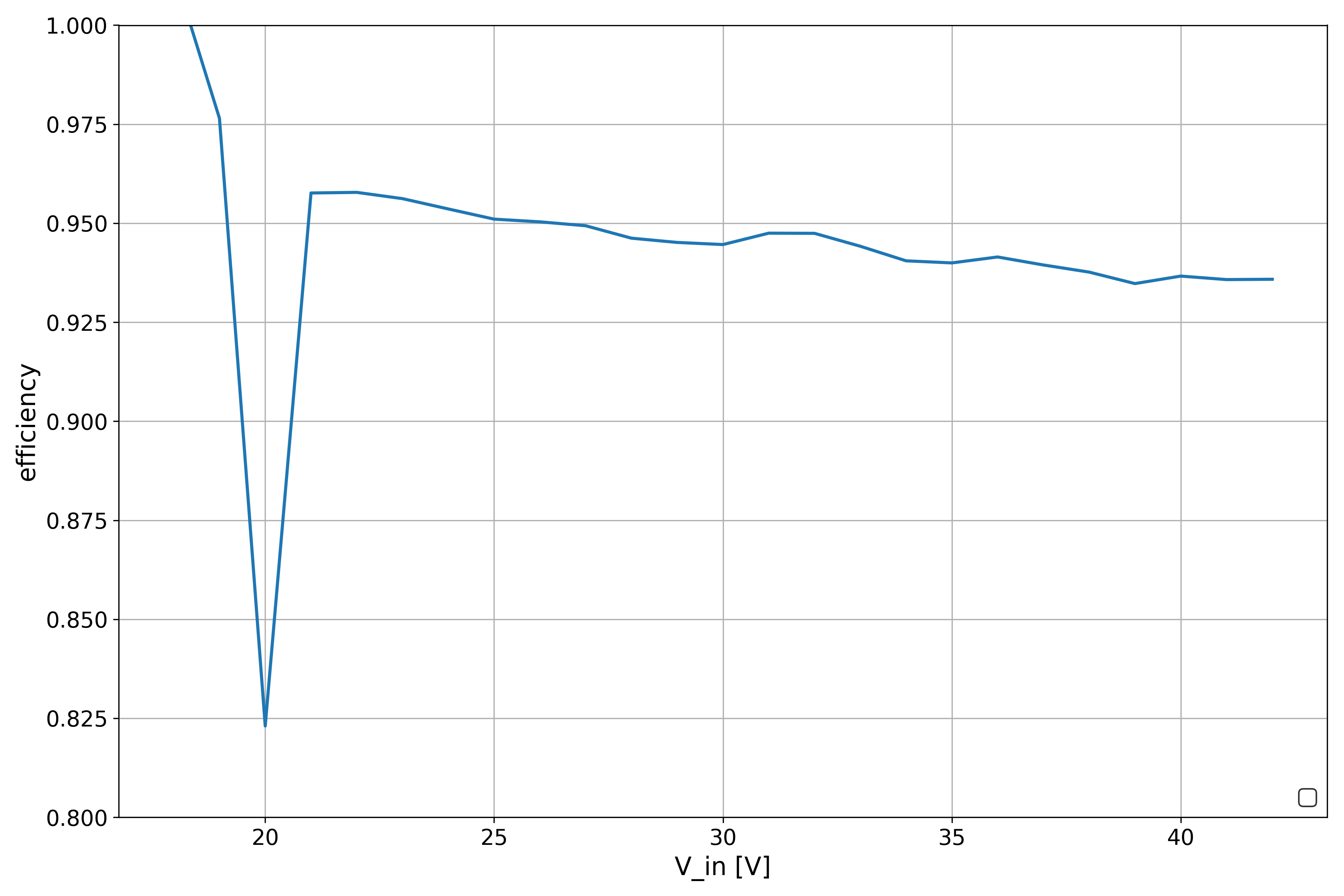 (LM3404 efficiency)
TODO: Replace graph with better data. Chip seems to be quite efficient.
The AL8860 is a hysteresis mode DC-DC step-down converter, designed for driving single or multiple series connected LEDs efficiently from a voltage source higher than the LED voltage. The device can operate from an input supply between 4.5V and 40V and provide an externally adjustable output current up to 1A for TSOT25 package and 1.5A for MSOP-8EP package.
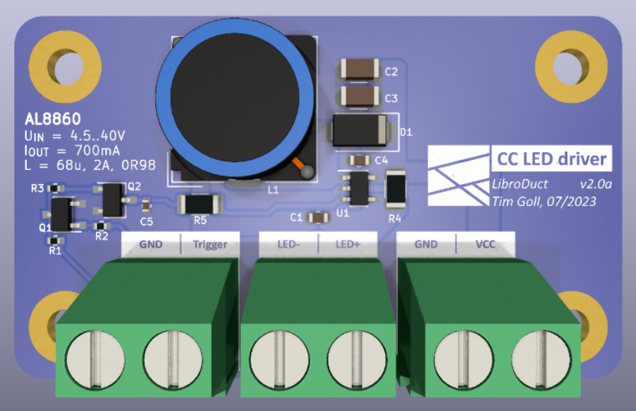 (AL8860 testing PCB render)
The curcuit designed is similar to the previous circuit but produces way better results thanks to the changed driving IC.
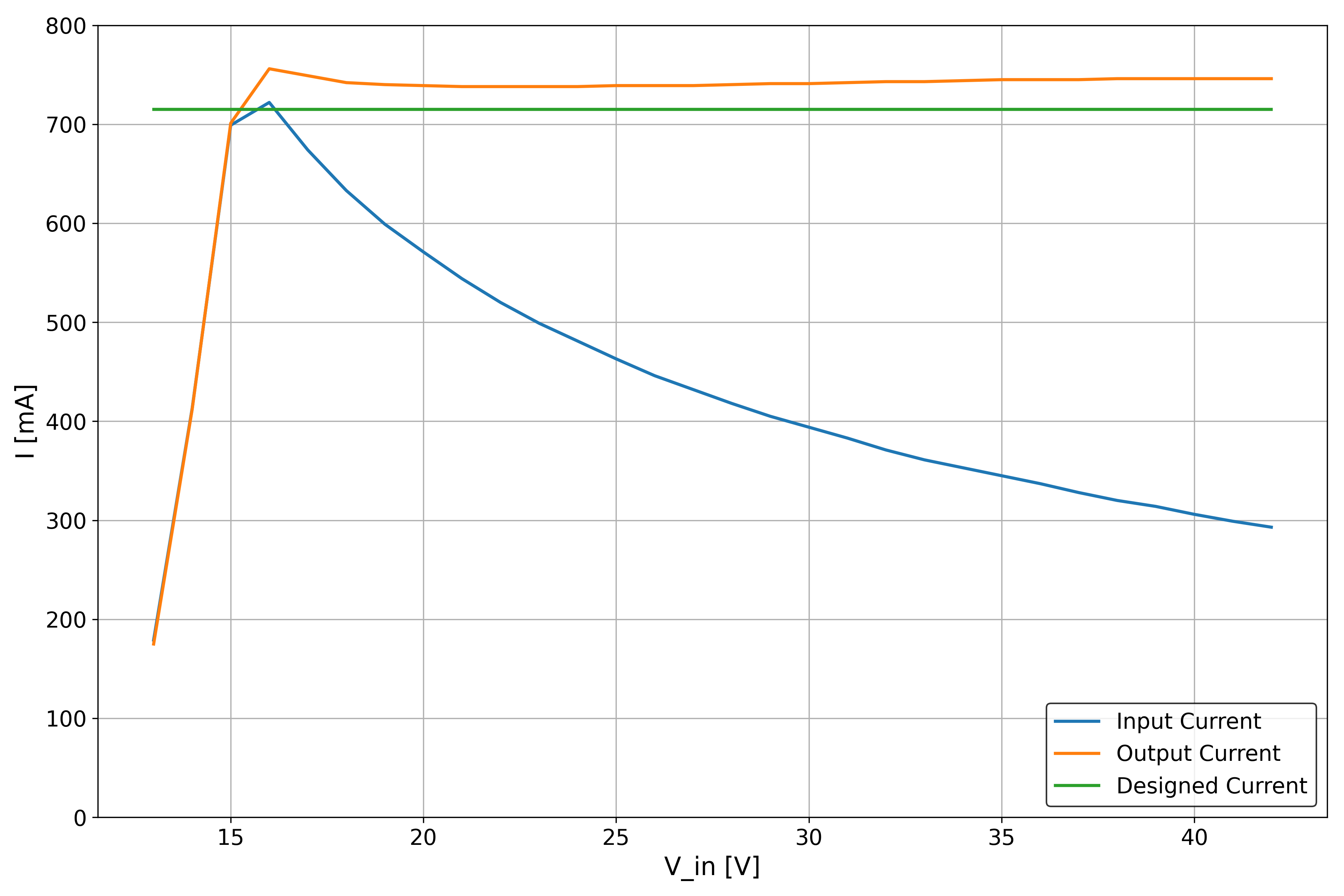 (AL8860 input and output current)
The above plot shows the input and output current. The output current is rather stable over the supported input voltage. This makes the circuit suitable for our needs.
It is also worth mentioning that the output current is a bit higher than the designed current. This is fine in our usecase but it is something to be aware of.
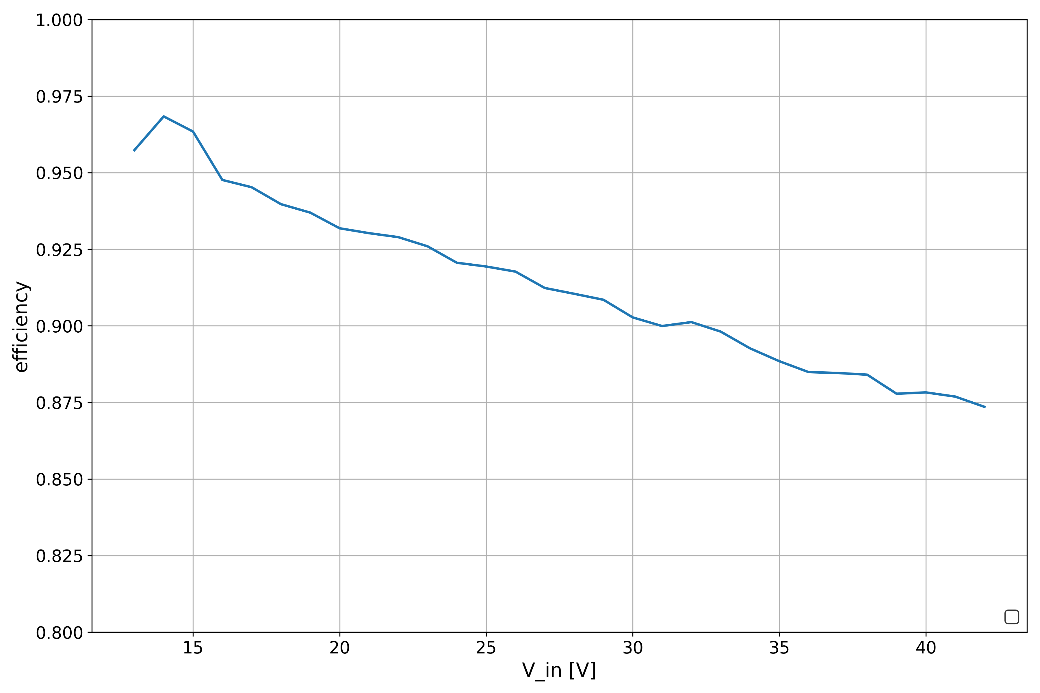 (AL8860 driver efficiency at 700mA)
Another test we did with these drivers is so test and asses the influence of different coils on the efficiency. Especially the influence of the DC resistance.
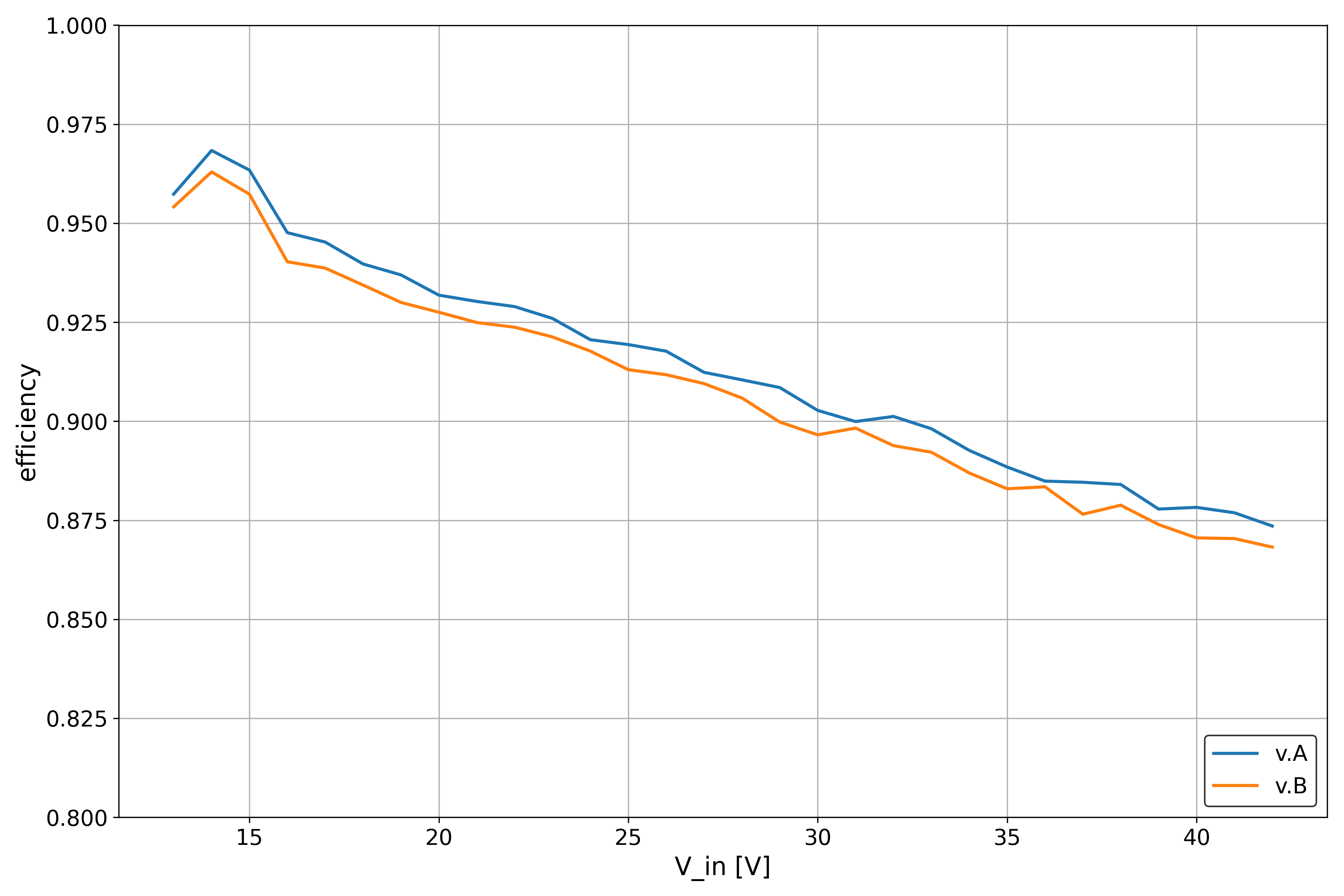 (AL8860 driver efficiency when tested with different coils)
The above plot shows the same AL8860 driver that was used previously, but we added another coil in the mix. v.A uses a coil with a DC resistance of 98mΩ, v.B has a DC resistance of 201mΩ. The inductance of both coils is identical.
It can be seen that the efficiency drops with higher DC resistance as this energy is lost in the form of heat created. It is therefore reasonable to use a bigger and better coil if the space is not constrained.
There is also an 1.5A version available of the driving IC. I tested it as well and got really good results. It seems to be a bit more efficient than the 700mA version. This could also be due to two LED strings being in parallel or the lower value of the shunt resistor.
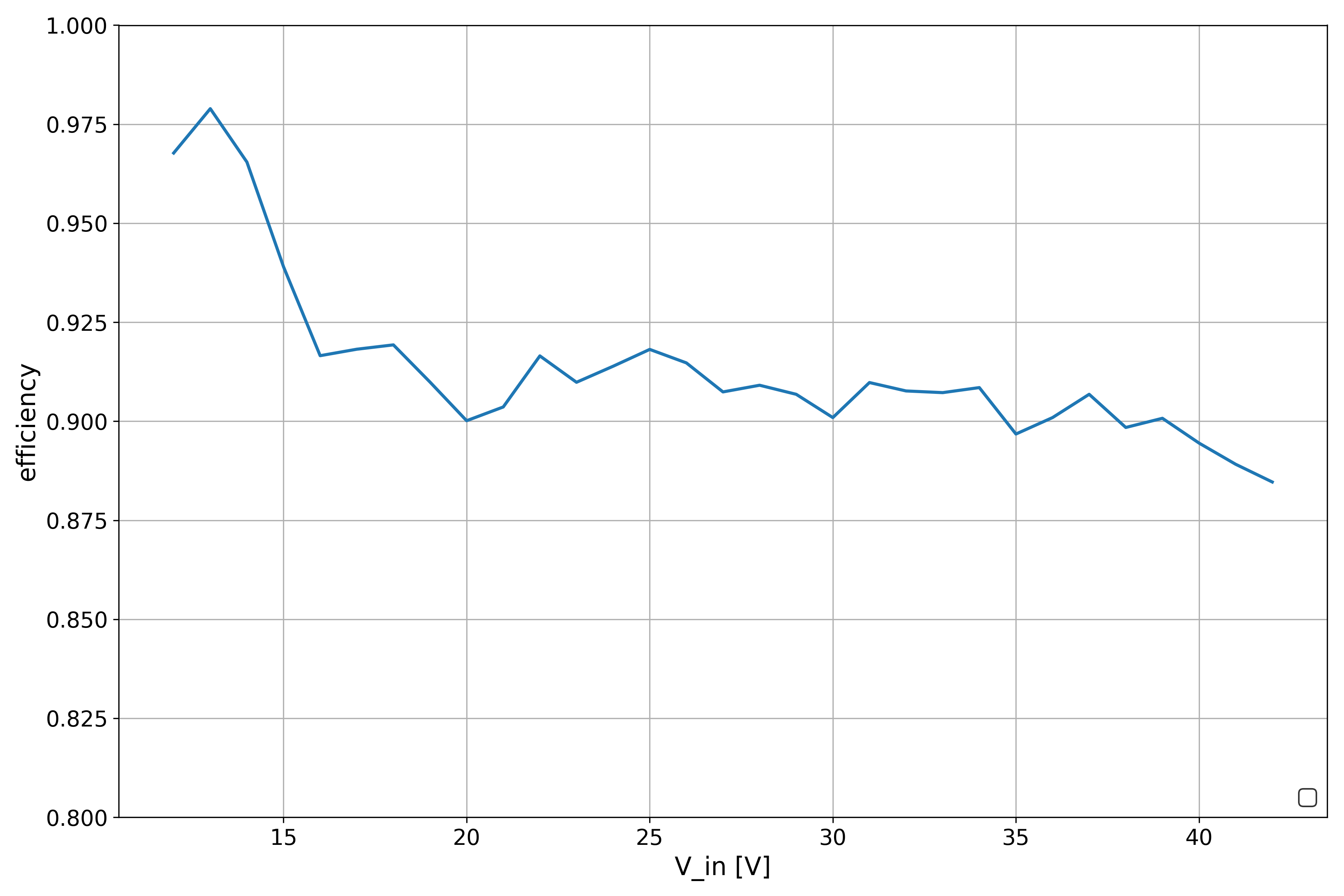 (AL8860MP driver efficiency at 1.5A)
There are many off-the-shelf LED driver modules available. One of them, the Meanwell LDD700LS was used here as a refernce point. When supplied with 36V at 700mA and a LED forward voltage of 14V, it seems to have an efficieny of 87%. Even in our worst case scenario our driver is more efficient.
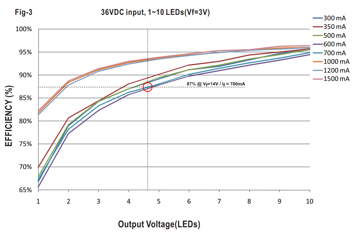 (LDD700LS driver module efficiency [fig 3, page 4])
Since the dimming pin of most LED driver ICs is open drain with a limited voltage range, we need additional circuitry to get what we need. Also many ICs support analog dimming with values over 100% if the internal ref voltage is surpassed which forces us to use the internal pullup.
The following circuit achieves all of that, while also supporting trigger voltages as high as VCC of the LED board, while also making sure that pulling the input to ground still disables it.
By default this circuit turns the device on and has to be actively turned off.
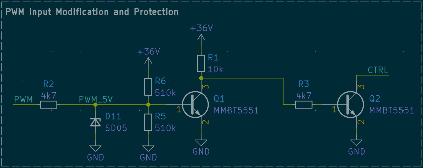 (PWM input modification schematic)
| Qty | Value | Footprint | References |
|---|---|---|---|
| 4 | MountingHole_Pad | MountingHole:MountingHole_3.2mm_M3_Pad_TopOnly | H1, H2, H3, H4 |
| 3 | Conn_01x02 | TerminalBlock_Phoenix:TerminalBlock_Phoenix_MKDS-1,5-2-5.08_1x02_P5.08mm_Horizontal | J1, J2, J3 |
| 2 | 100n | Capacitor_SMD:C_0603_1608Metric | C1, C4 |
| 2 | 4k7 | Resistor_SMD:R_0402_1005Metric | R2, R3 |
| 2 | 4u7 | Capacitor_SMD:C_1206_3216Metric | C2, C3 |
| 2 | MMBT5551 | Package_TO_SOT_SMD:TSOT-23 | Q1, Q2 |
| 1 | 0R | Resistor_SMD:R_1206_3216Metric | R5 |
| 1 | 0R140 | Resistor_SMD:R_1206_3216Metric | R4 |
| 1 | 10k | Resistor_SMD:R_0402_1005Metric | R1 |
| 1 | 330p | Capacitor_SMD:C_0402_1005Metric | C5 |
| 1 | 68u | Inductor_SMD:L_TDK_SLF12565 | L1 |
| 1 | AL8860WT | Package_TO_SOT_SMD:TSOT-23-5 | U1 |
| 1 | SS210 | Diode_SMD:D_SMA | D1 |
DIaLOGIKa-GmbH/pcb_constant-current-driver
Testing PCBs for different constant current driver ICs

VIPQualityPost/lemon-pepper-stepper
simplefoc all-in-one 50W hybrid stepper + bldc driver


sbyd-space/vape-light
An educational DIY kit for converting a disposable vape into a rechargeable flashlight


practable/ripple-tank
Software and documentation for the ripple tank remote lab project


jackw01/scanlight
A better light source for scanning color negative film
It measures 53.3 × 31.8 mm and has 2 copper layers, 1.6 mm thick.
22 parts, built around the AL8860WT, MMBT5551 and SS210. The full list of its parts is on this page, with links to each part's symbol and footprint where PCBKit's library has them.
From the DIaLOGIKa-GmbH/pcb_constant-current-driver repository on GitHub, at the commit this page was made from: the board is constant_current_driver_AL8860/constant_current_driver_AL8860.kicad_pcb and its schematic constant_current_driver_AL8860/constant_current_driver_AL8860.kicad_sch. PCBKit opens the board in the browser, with nothing to install.
Its repository publishes it under the MIT licence: you may reuse it on that licence's terms (keep the author's notice, and for a copyleft licence share your changes alike).