2 layers60 × 60 mm

 CoolNamesAllTaken/scbs4
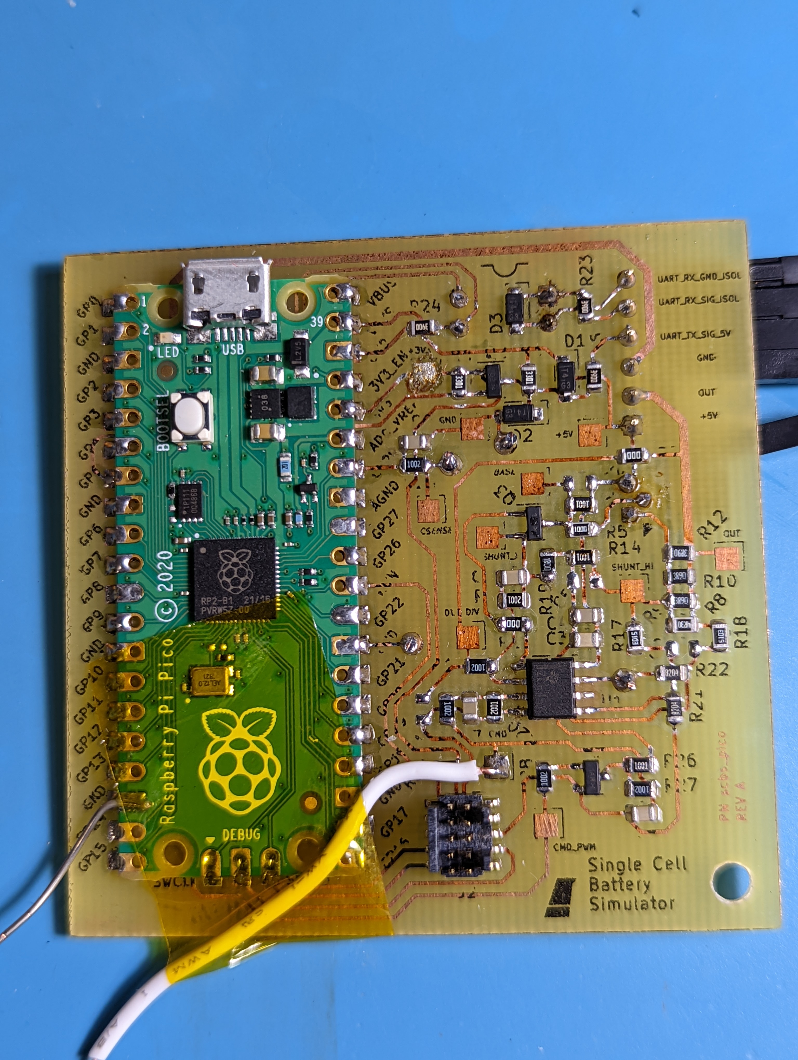
Single Cell Battery Simulator for testing a BMS.
Scbs pico is an open-source printed circuit board by CoolNamesAllTaken, from the CoolNamesAllTaken/scbs repository on GitHub. It is a 2-layer board of 60 × 60 mm with 64 parts on 64 nets, routed with 377 tracks and 4 vias.
It is built around the SC0915, TLV9062IDR-MS and 1N4148W-TP, with the MMBT3904, PN2907ATF and PREC006SBAN-M71RC among its other parts. Its parts include 29 resistors, 9 capacitors, 4 transistors, 3 ICs and 3 diodes. It belongs with the power boards and the RP2040 boards of this library.


Single Cell Battery Simulator for testing a BMS.
Cellsim 4S is a low-current battery pack simulator that simulates four battery cells in series. Each cell has a settable output voltage between 2.5-4.5V and a readable output current. Communication is done over a 9600 baud UART link using a custom serial protocol.
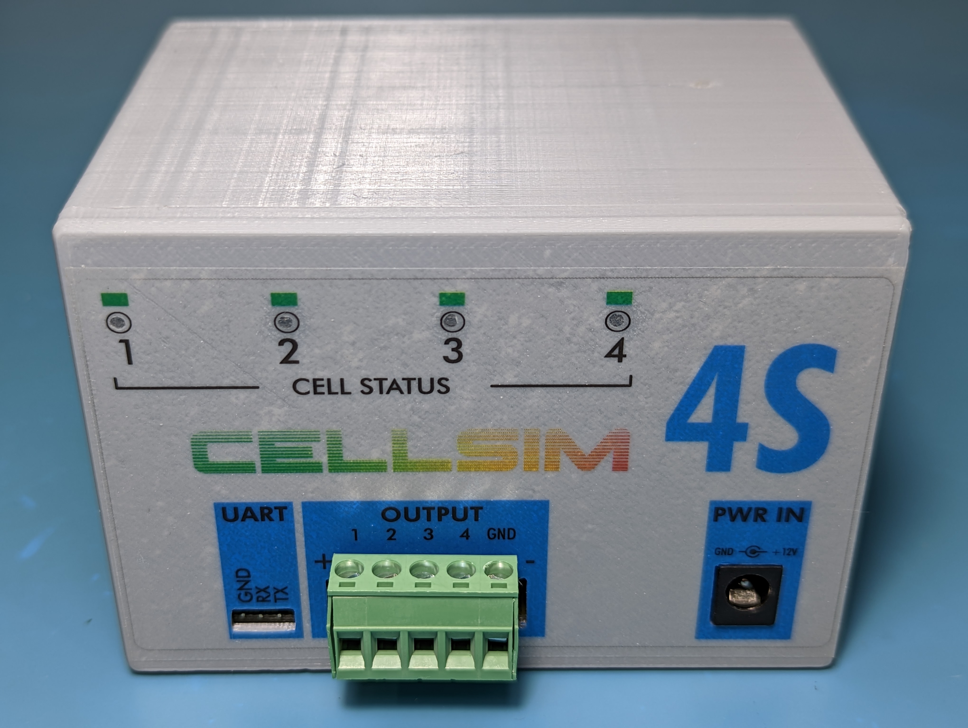
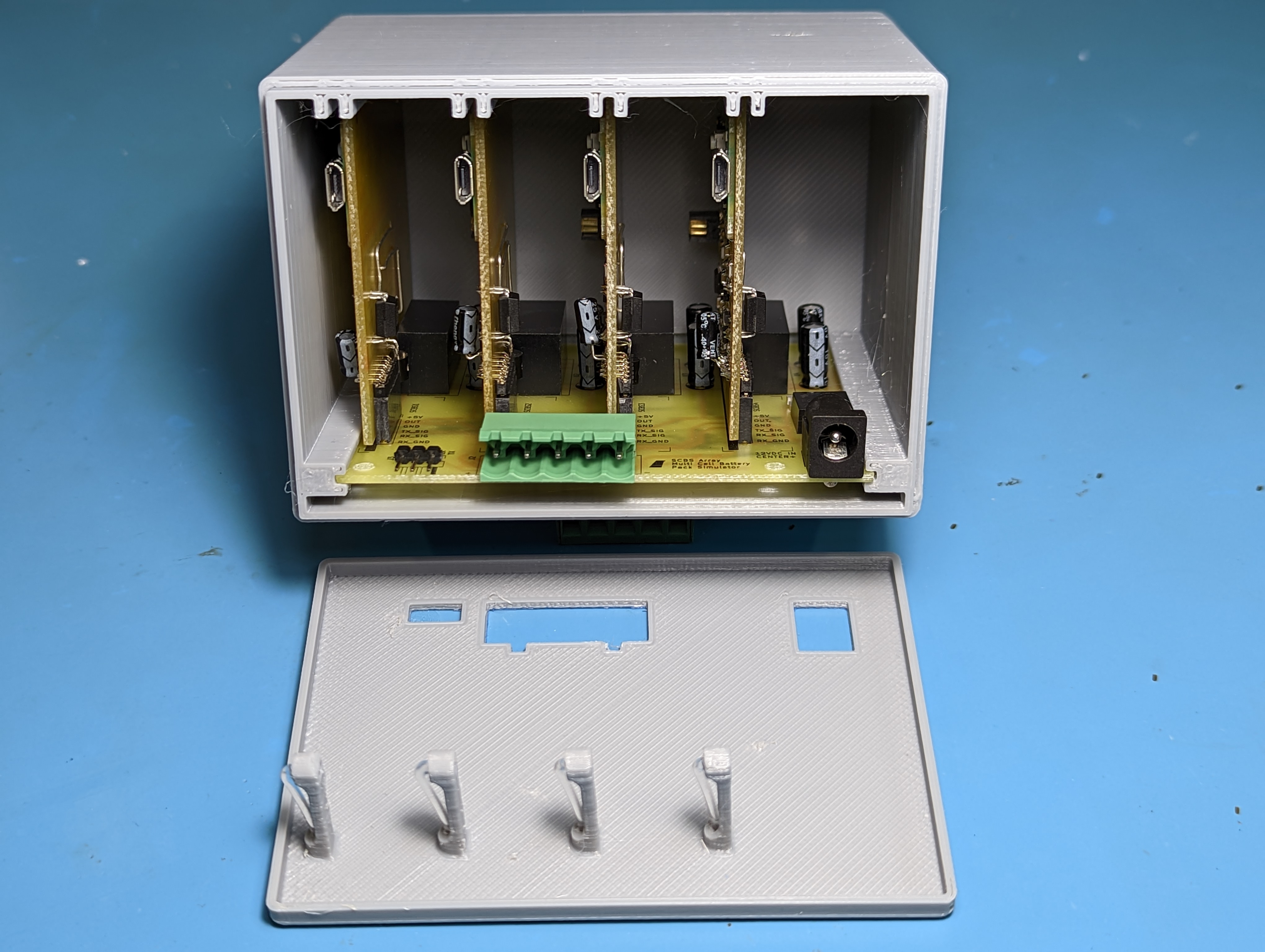
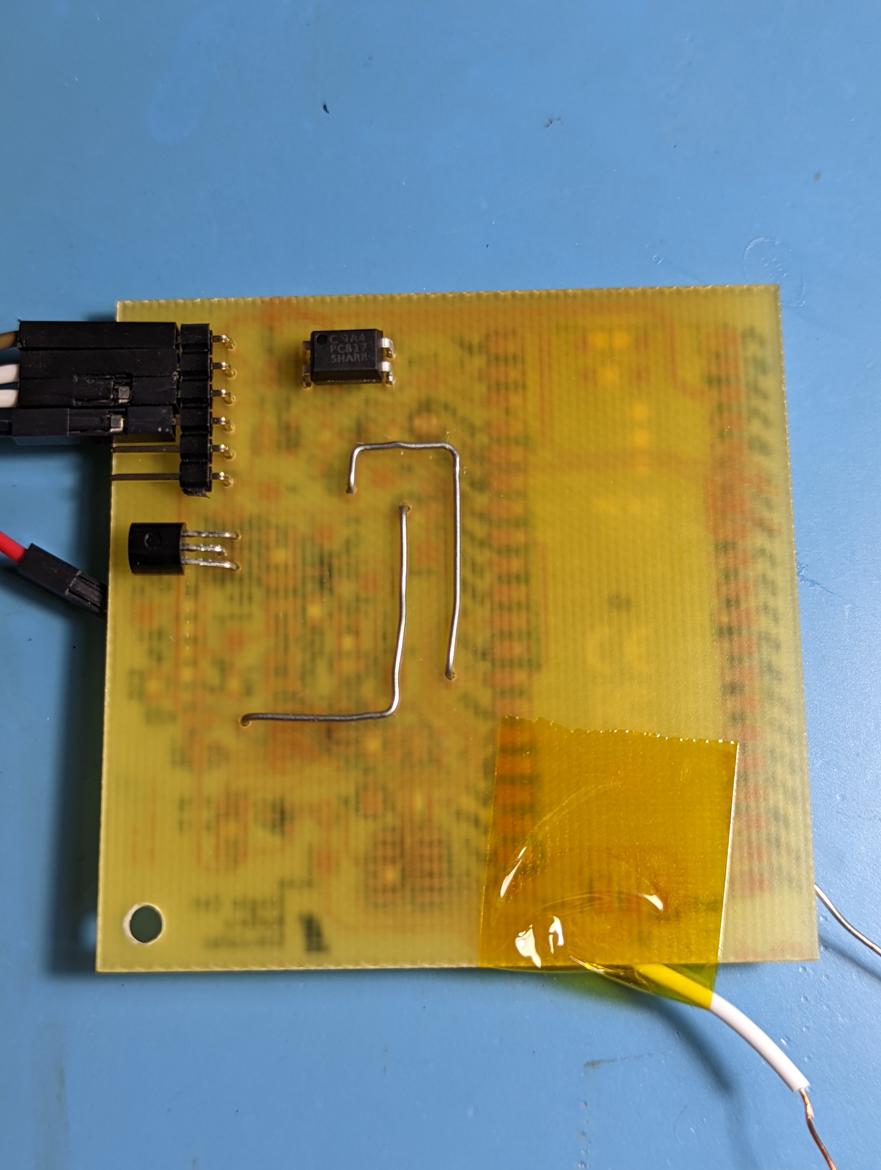
SCBS Pico is a single battery cell simulator that can be daisy chained with other devices of the same type in order to build a full simulated battery pack. It is the basic building block of the CELLSIM 4S.
| Qty | Value | Footprint | References |
|---|---|---|---|
| 11 | TestPoint | TestPoint:TestPoint_Pad_2.0x2.0mm | TP1, TP2, TP3, TP4, TP5, TP6, TP7, TP8, TP9, TP10, TP11 |
| 4 | 10k | Resistor_SMD:R_0805_2012Metric | R25, R27, R28, R30 |
| 3 | 0.1uF | Capacitor_SMD:C_0805_2012Metric | C4, C8, C9 |
| 3 | 1N4148 | Diode_SMD:D_SOD-123 | D1, D2, D3 |
| 3 | 1k | Resistor_SMD:R_0805_2012Metric | R2, R14, R26 |
| 3 | 3.9R 1% 0805 | Resistor_SMD:R_0805_2012Metric | R8, R9, R10 |
| 3 | 390R | Resistor_SMD:R_0805_2012Metric | R6, R23, R24 |
| 3 | DNP | Capacitor_SMD:C_0805_2012Metric | C2, C5, C6 |
| 2 | 10M | Resistor_SMD:R_0805_2012Metric | R11, R15 |
| 2 | 1nF | Capacitor_SMD:C_0805_2012Metric | C1, C7 |
| 2 | 2M | Resistor_SMD:R_0805_2012Metric | R1, R20 |
| 2 | 3k3 | Resistor_SMD:R_0805_2012Metric | R3, R4 |
| 2 | 510k 1% | Resistor_SMD:R_0805_2012Metric | R17, R18 |
| 2 | 8.2M 1% | Resistor_SMD:R_0805_2012Metric | R21, R22 |
| 2 | MMBT3904 | Package_TO_SOT_SMD:SOT-23 | Q3, Q4 |
| 1 | 0R | Resistor_SMD:R_0805_2012Metric | R7 |
| 1 | 100R | Resistor_SMD:R_0805_2012Metric | R13 |
| 1 | 1R | Resistor_SMD:R_0805_2012Metric | R19 |
| 1 | 1uF | Capacitor_SMD:C_0805_2012Metric | C3 |
| 1 | 2N2907 | Package_TO_SOT_THT:TO-92 | Q1 |
| 1 | 2N7002 | Package_TO_SOT_SMD:SOT-23 | Q2 |
| 1 | 4.3R 1% 0805 | Resistor_SMD:R_0805_2012Metric | R12 |
| 1 | 750R | Resistor_SMD:R_0805_2012Metric | R5 |
| 1 | Conn_01x06_Male | Connector_PinHeader_2.54mm:PinHeader_1x06_P2.54mm_Horizontal | J1 |
| 1 | Conn_ARM_JTAG_SWD_10 | Connector_PinHeader_1.27mm:PinHeader_2x05_P1.27mm_Vertical_SMD | J2 |
| 1 | DNP | Resistor_SMD:R_0805_2012Metric | R16 |
| 1 | Graphic | Custom_Graphic:bird_with_pants_small_flipped | GRAPHIC1 |
| 1 | MountingHole | MountingHole:MountingHole_3.2mm_M3 | H1 |
| 1 | PC817 | Package_DIP:DIP-4_W7.62mm | U2 |
| 1 | PCB | Custom_Graphic:PCB_PN_REV_small | PCB1 |
| 1 | Pico | Custom_Module:RPi_Pico_SMD_TH | U3 |
| 1 | TLV9062xD | Package_SO:SOIC-8_3.9x4.9mm_P1.27mm | U1 |


bitraf/blyant
Bitraf's musikalske blyant. Et byggesett for å lære seg å lodde, som du også kan ha masse morro med.


tinyvision-ai-inc/UPduino-v3.0
UPduino 3.0: new 4 layer layout, various other improvements

Brunner-neutrino-lab/ets-breakout
This repository contains the complete design files for a 96-channel I-V curve pulse multiplexer used in detector physics instrumentation.

libertathiest/fs10-atmega32u4-monitor
A standalone USB monitor and configuration tool for the FCI FS10 Flow Switch, built around the ATmega32U4 on an Arduino Leonardo–compatible board.

trfaa001/Potentiometer-pedals-to-USB
Arduino project that uses potentiometers as game pedals.

It measures 60 × 60 mm and has 2 copper layers, 1.6 mm thick.
64 parts, built around the SC0915, TLV9062IDR-MS, 1N4148W-TP and MMBT3904. The full list of its parts is on this page, with links to each part's symbol and footprint where PCBKit's library has them.
From the CoolNamesAllTaken/scbs repository on GitHub, at the commit this page was made from: the board is kicad/scbs_pico/scbs_pico.kicad_pcb and its schematic kicad/scbs_array/scbs_array.kicad_sch. PCBKit opens the board in the browser, with nothing to install.
Its repository states no licence, so its author keeps all rights: ask CoolNamesAllTaken before reusing the design.