2 layers139.7 × 63.5 mm
Thermostat V2
Connicpu/thermostat
DIY Zigbee thermostat (ESP32-C6) with day/night schedule and a Home Assistant Lovelace card
72 partsMIT

 Connicpu/thermostat
DIY Zigbee thermostat (ESP32-C6) with day/night schedule and a Home Assistant Lovelace card
Thermostat v3 is an open-source printed circuit board by Connicpu, from the Connicpu/thermostat repository on GitHub, published under the MIT licence. It is a 2-layer board of 140 × 64 mm with 101 parts on 79 nets, routed with 916 tracks and 79 vias.
It is built around the ESP32-C6-WROOM-1-N8, T405-600B and LMR16006XDDCR, with the SHT40-AD1B-R2, MOC3063S and STWD100NYWY3F among its other parts. Its parts include 33 resistors, 27 capacitors, 8 ICs, 8 diodes and 5 switches. It belongs with the home automation and IoT and radio and wireless boards and the ESP32 and RISC-V boards of this library.


Shared as-is — not seeking contributions or pull requests.
ESP32-C6 Zigbee thermostat for single-stage HVAC (R/C/W/Y/G), with e-paper display, SHT40 temperature/humidity sensor, and triac outputs. Designed for JLCPCB assembly.
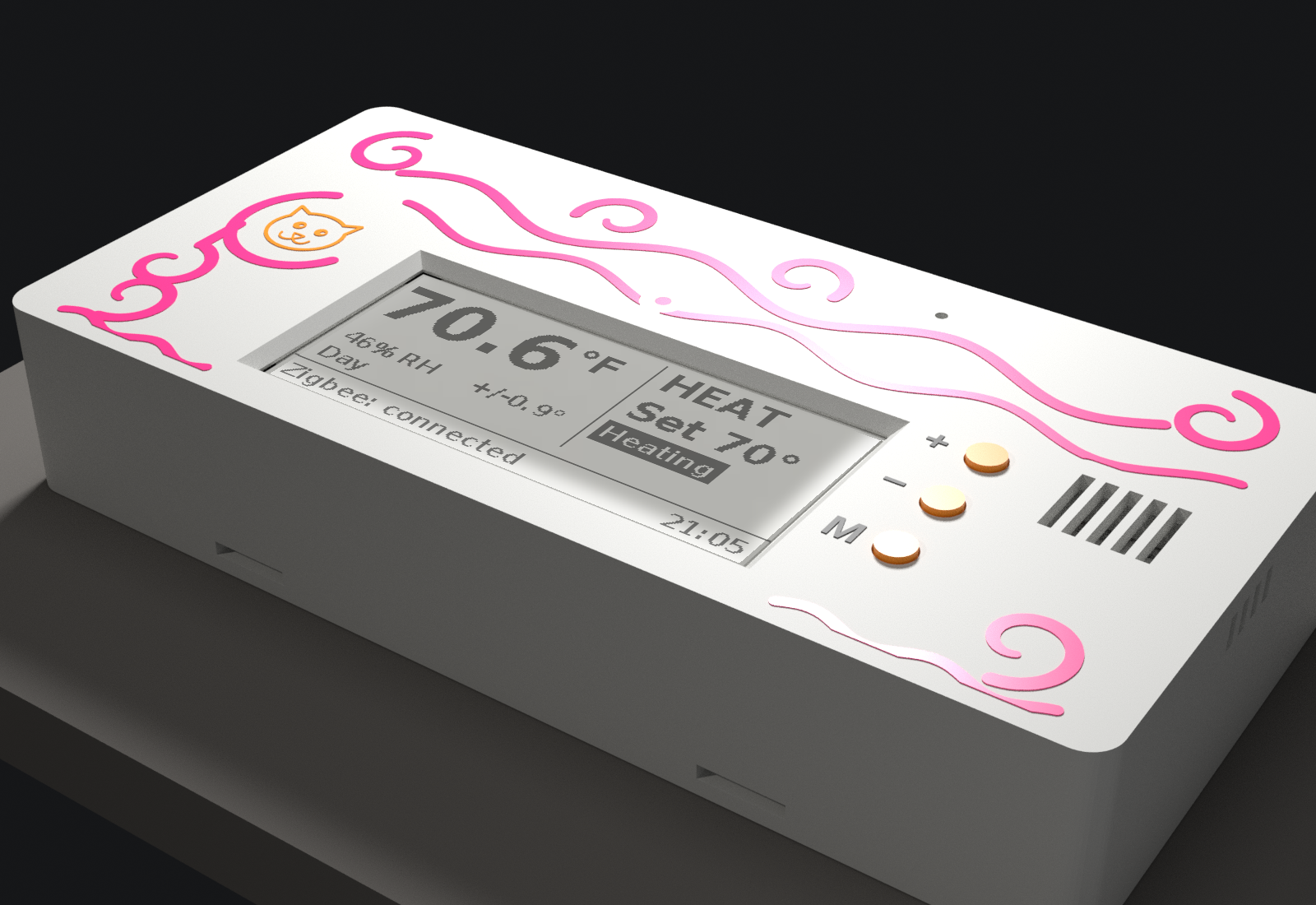
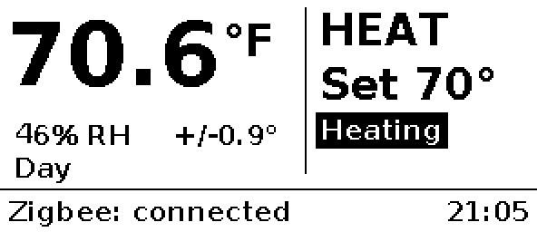
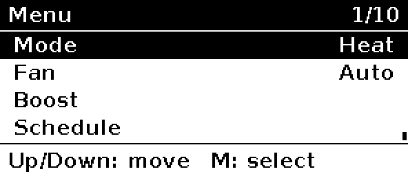
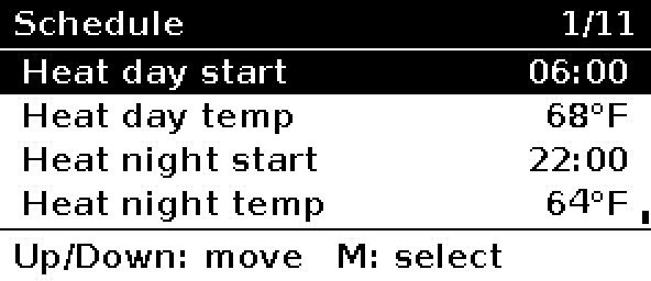
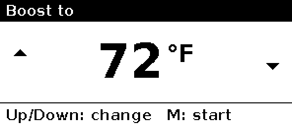
On-device screens (296×128 e-paper, shown at 2×; °F):
| Home | Menu |
|---|---|
 |  |
| Schedule | Boost to |
 |  |
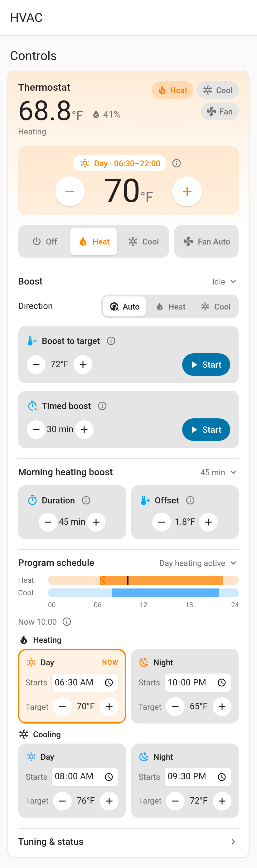
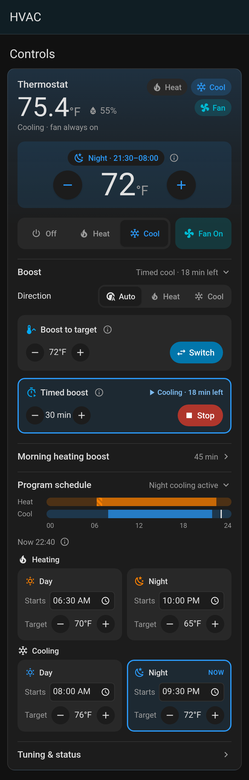
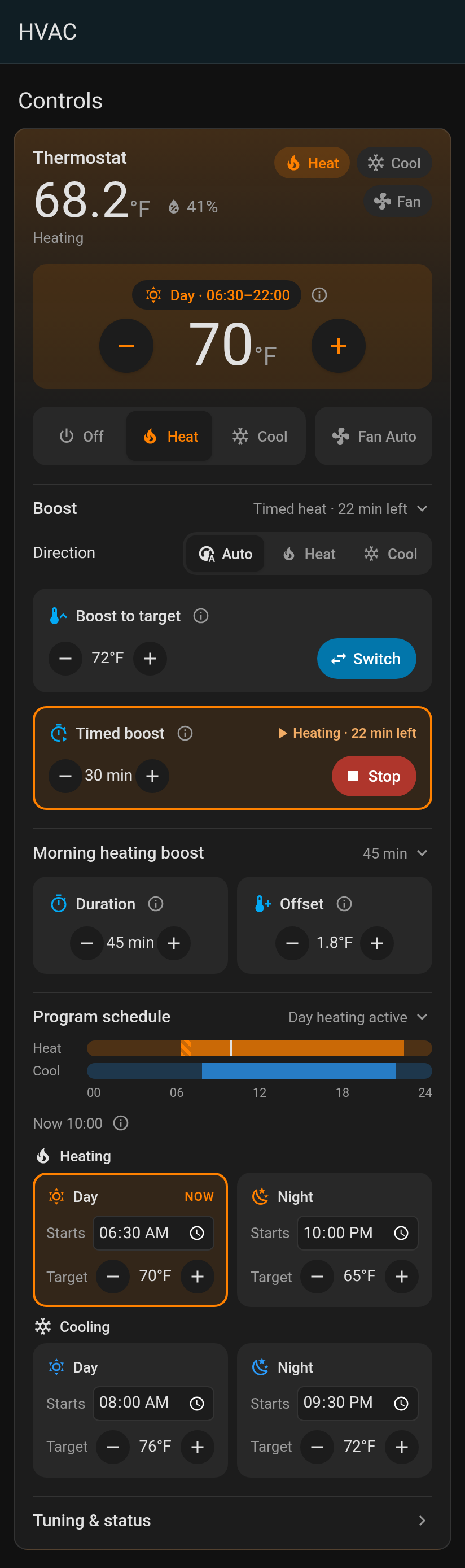
Home Assistant Lovelace card (install):
| Heat, day (light) | Cool, night (dark) | Timed heat boost (dark) |
|---|---|---|
 |  |  |
More: case renders in case/, every menu screen in firmware/README.md.
The case (case/thermostat_case.scad) is a 147 × 71 × 26.25 mm PETG shell, backplate, and panel carrier for a Bambu P2S with a 0.4 mm nozzle. The carrier holds the display panel with its nominal back 4.45 mm above the board. The panel rests on stops 0.15 mm under that, located by the long-edge fences and the cable-end posts. Four bridges in the shell press the border. The flex plugs into J4 with the display panel seated on the stops. A thin corner can leave J4; the shell comes off, the tail is pressed back in, and the slider is closed. A fingernail shuts the slider on the ear's +x face, and a fingertip on the carrier push opens it toward +x. The shell clips to the backplate. It does not clamp the board. The three buttons snap into the face from the inside and stay in the shell. Each cap is a 65° cone and one 0.40 mm leaf. The leaf is a cantilever, free length 4.35 mm, and it only keeps the cap in the face. The print adds a 0.34 mm nub on the cone top under the free end so the leaf's bed-facing face is a bridge, and that nub is snapped off before the cap goes into the tube. case/ASSEMBLY.md is the build order, the fold dimensions, and the service steps.
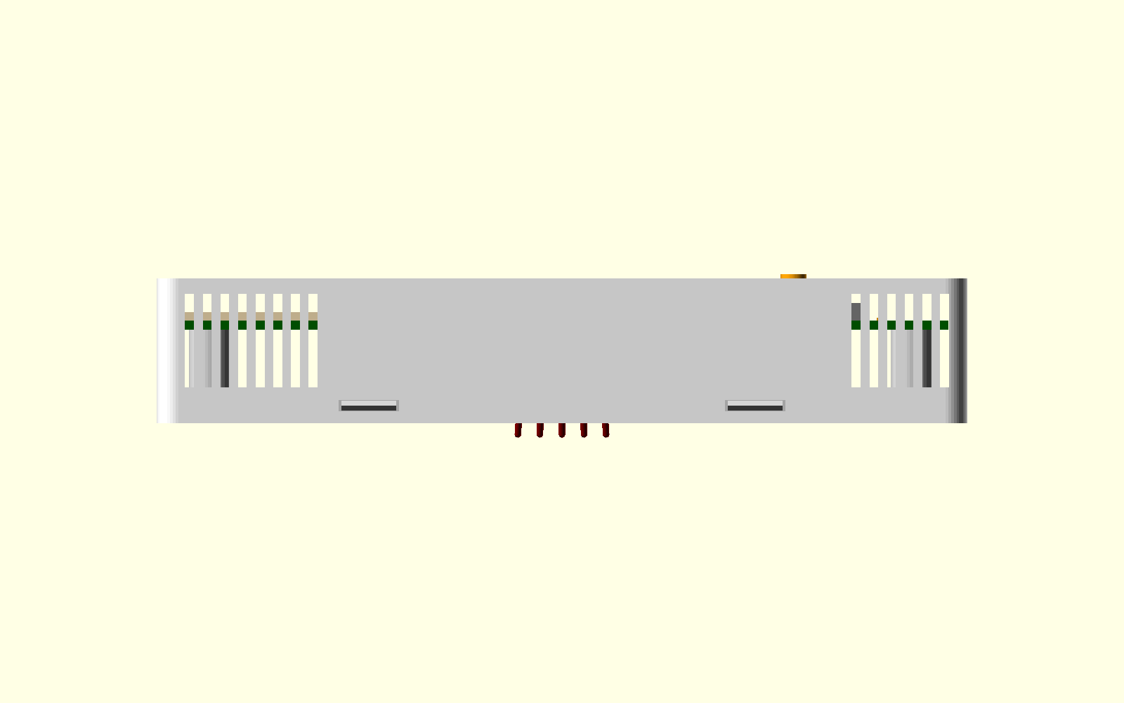
Air inside the case is split into three zones:
The ribs stop 0.4 mm short of the board, and above the lip they run out to the lip's outer face so they come within 0.3 mm of the shell. The zone walls keep at least 0.5 mm off the parts, including the USB-C shield legs and locating peg on the back of the board. Front clearances include the ±0.16 mm board-thickness tolerance.
Expected benefit. A zonal model puts the triac-induced sensor rise about 10–25% lower than the same case with one undivided cavity (no ribs, partition, or curtain). That is a model, not a measurement. Most of the remaining error is heat flowing along the PCB ground pour, which a case cannot stop, and the vents themselves carry only a small share of the hot zone's heat. The walls matter more than the hole count: they also help keep wall-cavity air from the wiring hole away from the sensor.
Check it. Log a heat call and a cool call against a reference thermometer, with a clamp meter on W, Y, and G. Taping the edge slots removes only the vents, about 6% of the modeled sensor rise; the ribs, partition, and curtain stay, so expect little difference. Measuring what the walls do needs a second print without the ribs, partition, and curtain. The two offsets add, so use only one. CONFIG_THERMO_SELF_HEAT_OFFSET_C100 is build-time (menuconfig, then a reflash) and defaults to 0. ZHA sets the thermostat's LocalTemperatureCalibration attribute, in 0.1 °C steps over ±2.5 °C, applied on top of that build-time offset. About −0.1 °C is an unmeasured guess until a reference-thermometer log exists.
board.stl is not in the repo. From the repo root, export the populated board with KiCad 9 (do not pass --drill-origin; scripts/case_fit.py places the model):
kicad-cli pcb export stl -o board.stl --force --cut-vias-in-body kicad/thermostat-v3.kicad_pcbThe script header also has the OpenSCAD lines for the assembly-frame back.stl, shell.stl, carrier.stl, and the seated and pressed button meshes it checks against. The flex fold, the tail insertion, the carrier clearances, and the button travel run even when board.stl is absent.
Warning: don't connect USB while 24VAC is wired unless you use a USB isolator. First-time flashing on Arch Linux: docs/flashing-arch.md.
This project is shared as-is. It is not seeking contributions or pull requests.
MIT — see LICENSE. Third-party notices (Lit, Material Design Icons, DejaVu/Bitstream, Espressif, Good Display sequences, LCSC STEP models, …) are in NOTICE.
This is a DIY thermostat that switches 24 VAC HVAC loads. Treat the Zigbee network perimeter as the security boundary:
esp_ota_*
(rollback via pending-verify exists). Anyone who can run an OTA server the device trusts can
push firmware. There is no image signature check.install_code_policy is false, so pairing uses the Zigbee 3.0
well-known trust-center link-key path (normal for Home Assistant / ZHA). Don't leave the
network open to joining when you aren't pairing.sdkconfig.defaults. Physical USB access to the
board gives a console.See also MANUFACTURER_ID.md for the Zigbee manufacturer code (0x434E:
this project's DIY code from the quiet 0x3000–0x5FFF band; not CSA-assigned, not certified).
E-paper driver sequences in firmware/components/display/ssd1680.c follow Good Display's
GDEY029T94 sample/datasheet (not a verbatim copy of their sample tree). Full attribution is
in NOTICE.
| Qty | Value | Footprint | References |
|---|---|---|---|
| 11 | 10k | Resistor_SMD:R_0402_1005Metric | R2, R5, R6, R7, R8, R9, R11, R12, R20, R30, R40 |
| 6 | 1uF 50V | Capacitor_SMD:C_0603_1608Metric | C30, C31, C32, C33, C34, C35 |
| 4 | 100nF | Capacitor_SMD:C_0402_1005Metric | C3, C8, C10, C11 |
| 4 | 10uF | Capacitor_SMD:C_0603_1608Metric | C4, C5, C7, C39 |
| 4 | 1uF | Capacitor_SMD:C_0402_1005Metric | C6, C9, C36, C38 |
| 4 | 4.7uF 100V X7R | Capacitor_SMD:C_1210_3225Metric | C1, C2, C41, C42 |
| 4 | M4 | MountingHole:MountingHole_4.3mm_M4 | H1, H2, H3, H4 |
| 3 | 100R | Resistor_SMD:R_0805_2012Metric | R22, R32, R42 |
| 3 | 100R DNP | Resistor_SMD:R_0805_2012Metric | R24, R34, R44 |
| 3 | 100nF 50V DNP | Capacitor_SMD:C_0805_2012Metric | C20, C21, C22 |
| 3 | 1k | Resistor_SMD:R_0805_2012Metric | R23, R33, R43 |
| 3 | 220R | Resistor_SMD:R_0402_1005Metric | R21, R31, R41 |
| 3 | B5819W | tstat:SOD-123_B5819W | D6, D7, D8 |
| 3 | MOC3063S | tstat:MOC3063S | U6, U7, U8 |
| 3 | T405-600B | tstat:TO-252-2_TRIAC_DPAK | Q2, Q3, Q4 |
| 2 | 4.7k | Resistor_SMD:R_0402_1005Metric | R13, R14 |
| 2 | 5.1k | Resistor_SMD:R_0402_1005Metric | R3, R4 |
| 2 | SS210 | tstat:SMA_SS210 | D3, D4 |
| 1 | +3V3 | tstat:TestPoint_Pad_D1.5mm | TP3 |
| 1 | 0.5A 60V PTC | tstat:F1812_PTC | F1 |
| 1 | 100k | Resistor_SMD:R_0402_1005Metric | R50 |
| 1 | 1M | Resistor_SMD:R_0402_1005Metric | R15 |
| 1 | 1k | Resistor_SMD:R_0402_1005Metric | R10 |
| 1 | 2.2R | Resistor_SMD:R_0603_1608Metric | R16 |
| 1 | 2.9in EPD FPC | tstat:FPC24_AFC07 | J4 |
| 1 | 22uH | Inductor_SMD:L_Sunlord_SWPA6045S | L1 |
| 1 | 3.3R 0.75W pulse | Resistor_SMD:R_1206_3216Metric | R51 |
| 1 | 33k | Resistor_SMD:R_0402_1005Metric | R1 |
| 1 | 4.7uF 25V | Capacitor_SMD:C_0805_2012Metric | C40 |
| 1 | 47uF 63V | tstat:CP_Radial_D8.0mm_P3.50mm | C43 |
| 1 | 47uH | Inductor_SMD:L_APV_ANR3015 | L2 |
| 1 | AO3400A | tstat:SOT-23_AO3400A | Q1 |
| 1 | BOOT | tstat:SW_TS1187A | SW2 |
| 1 | DOWN | tstat:SW_TS1187A | SW4 |
| 1 | ESP32-C6-WROOM-1-N8 | tstat:ESP32-C6-WROOM-1 | U3 |
| 1 | GND | tstat:TestPoint_Pad_D1.5mm | TP2 |
| 1 | HVAC R C W Y G | tstat:HVAC_TERM_15EDGRC | J1 |
| 1 | LMR16006XDDCR | tstat:SOT-23-6_LMR16006 | U1 |
| 1 | LOGO | LOGO_CAT | LOGO1 |
| 1 | MB10S | tstat:MBS_MB10S | D1 |
| 1 | MODE | tstat:SW_TS1187A | SW5 |
| 1 | RED | tstat:LED_0603_KT | D5 |
| 1 | RESET | tstat:SW_TS1187A | SW1 |
| 1 | SHT40-AD1B | Sensor_Humidity:Sensirion_DFN-4_1.5x1.5mm_P0.8mm_SHT4x_NoCentralPad | U5 |
| 1 | SMBJ40CA | tstat:D_SMB_TVS | D2 |
| 1 | STWD100NYWY3F | tstat:SOT-23-5_STWD100 | U4 |
| 1 | Stemma QT | tstat:JST_SH4_STEMMA | J3 |
| 1 | UP | tstat:SW_TS1187A | SW3 |
| 1 | USB-C | tstat:USB_C_Receptacle_HRO_TYPE-C-31-M-12 | J2 |
| 1 | USBLC6-2SC6 | tstat:SOT-23-6_USBLC6 | U2 |
| 1 | VBUS | tstat:TestPoint_Pad_D1.5mm | TP4 |
| 1 | VIN_HV | tstat:TestPoint_Pad_D1.5mm | TP1 |
Connicpu/thermostat
DIY Zigbee thermostat (ESP32-C6) with day/night schedule and a Home Assistant Lovelace card

slippery-carrot/ESPrinkler-Retic-Controller
8-Zone reticulation controller based on ESPHome for Home Assistant

ciaassured/eveningstar-hardware
Hardware design for the Eveningstar ESP32-based Morningstar MeterBus interface.

eerdemgundogdu/avtech-agv-main
Software and carrier PCB design for a line-following forklift AGV built by CU AVTECH for the Sanayide Robotik Uygulamalar 2026 competition.


It measures 140 × 64 mm and has 2 copper layers, 1.6 mm thick.
101 parts, built around the ESP32-C6-WROOM-1-N8, T405-600B, LMR16006XDDCR and SHT40-AD1B-R2. The full list of its parts is on this page, with links to each part's symbol and footprint where PCBKit's library has them.
From the Connicpu/thermostat repository on GitHub, at the commit this page was made from: the board is kicad/thermostat-v3.kicad_pcb and its schematic kicad/thermostat-v3.kicad_sch. PCBKit opens the board in the browser, with nothing to install.
Its repository publishes it under the MIT licence: you may reuse it on that licence's terms (keep the author's notice, and for a copyleft licence share your changes alike).