
2 layers127 × 73.7 mm

 ClockWorks001/PIC16F1705_MelodyTimer5
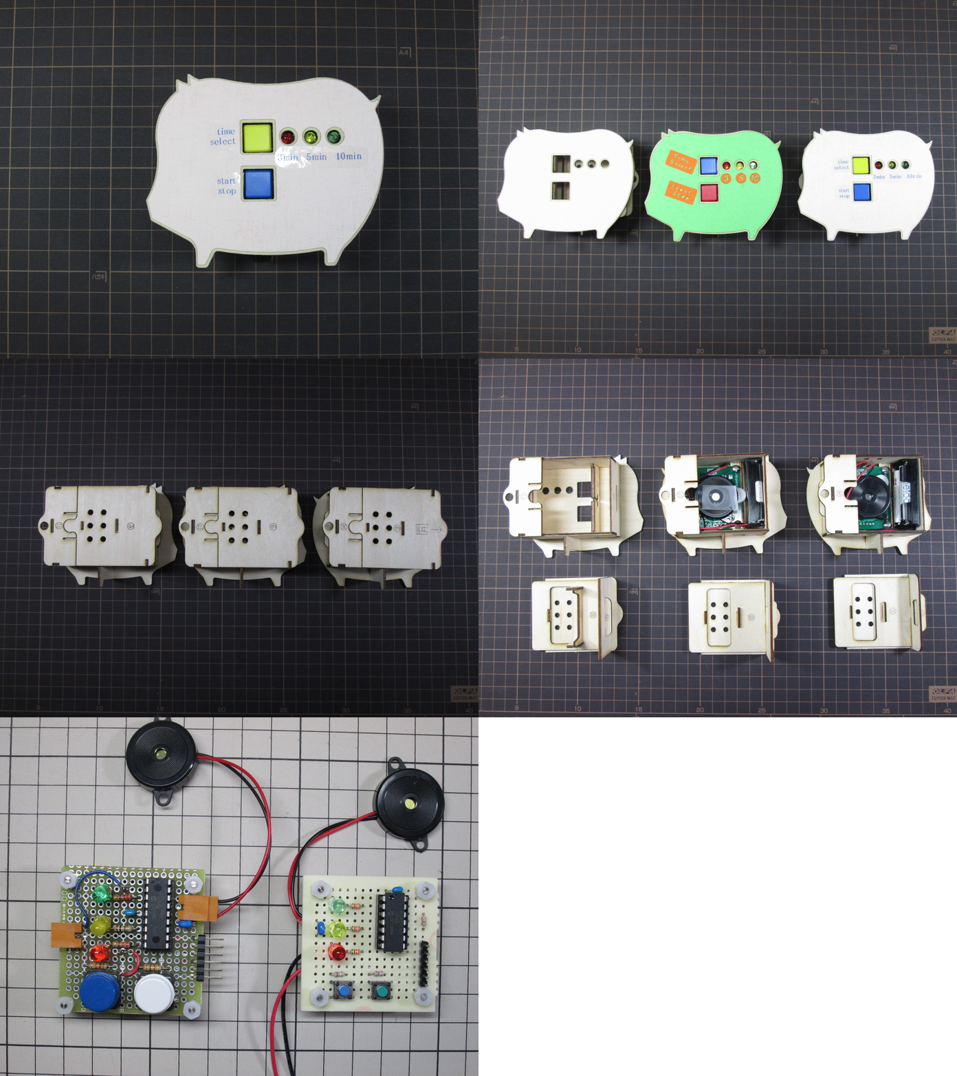
This is a simple kitchen/cooking timer by [PIC16F1705][1]. It can choose which of 3 minutes, 5 minutes and 10 minutes. When it became end of time, it sounds a melody.
PIC16F1705 MelodyTimer5 is an open-source printed circuit board by ClockWorks001, from the ClockWorks001/PIC16F1705_MelodyTimer5 repository on GitHub. It is a 2-layer board of 50 × 50 mm with 26 parts on 16 nets, routed with 120 tracks and 1 via.
It is built around the PIC16F1705-I/P. Its parts include 6 resistors, 6 connectors, 3 diodes, 2 capacitors and 2 switches. It belongs with the PIC boards of this library.
This is a simple kitchen/cooking timer by PIC16F1705. It can choose which of 3 minutes, 5 minutes and 10 minutes.
This is a simple kitchen/cooking timer by PIC16F1705. It can choose which of 3 minutes, 5 minutes and 10 minutes. When it became end of time, it sounds a melody.
I use following peripherals for this Melody Timer project. TMR1 (with interrupt. It makes 1mil second interval.) TMR2 ECCP2(with TMR2. I use it for PWM output. It buzz a piezo sounder.) GPIO(input x2 for Switches, output x3 for LED1, LED2, LED3)
Other references. You can see in the "PIC16F1705_MelodyTimer5_20150426.ods" file.
I created this project using the free versions of the following tools:
You will need to download and install these tools appropriately before you can open this project and build it. I use the Microchip MPLAB PICkit3 In-Circuit Debugger to program the chip and debug it.
Hiroshi Murakami
https://github.com/ClockWorks001
| Qty | Value | Footprint | References |
|---|---|---|---|
| 4 | PAD3mmX5mm | P1, P2, P3, P4 | |
| 4 | Val** | HOLE1.5mm | H?, H?, H?, H? |
| 3 | 10K | R4_MU | R4, R5, R6 |
| 3 | 240 | R4_MU | R1, R2, R3 |
| 3 | LED | LED-5MM_AK | D1, D2, D3 |
| 2 | SW_PUSH | SW_PUSH-12mm+_AK | SW1, SW2 |
| 1 | 0.1uF | C1_MU | C2 |
| 1 | 10uF | C1_MU | C1 |
| 1 | BATTERY | CR2032H_AK | BT1 |
| 1 | CN-ICSP | PINHEAD1-6_MU | CN2 |
| 1 | CN-POWER | PINHEAD1-2_MU2 | CN1 |
| 1 | PIC16F1705 | DIP-14__300_MU | U1 |
| 1 | SPEAKER | PINHEAD1-2_MU2 | SP1 |


hackclub/OnBoard
💡 Join 1,000 teenagers and make your first PCB with a $100 grant!


harbaum/galagino
A Galaga, Pac-Man and Donkey Kong arcade emulator for the ESP32

Luos-io/luos_engine
Open-source and real-time orchestrator for cyber-physical-systems, to easily design, test and deploy embedded applications and digital twins.
It measures 50 × 50 mm and has 2 copper layers, 1.6 mm thick.
26 parts, built around the PIC16F1705-I/P. The full list of its parts is on this page, with links to each part's symbol and footprint where PCBKit's library has them.
From the ClockWorks001/PIC16F1705_MelodyTimer5 repository on GitHub, at the commit this page was made from: the board is KICAD/PIC16F1705_MelodyTimer5.kicad_pcb. PCBKit opens the board in the browser, with nothing to install.
Its repository states no licence, so its author keeps all rights: ask ClockWorks001 before reusing the design.