4 layers90.8 × 60.5 mm

 ChrisKlein01/ArrozPCB
LoRa-based GPS PCB design with KiCad
PCB LoRa+GPS is an open-source printed circuit board by ChrisKlein01, from the ChrisKlein01/ArrozPCB repository on GitHub. It is a 4-layer board of 80 × 50 mm with 84 parts on 102 nets, routed with 605 tracks and 208 vias.
It is built around the ESP32-PICO-D4, TESEO-LIV3R and TPS62A01ADRL, with the BQ24074RGTR, RFM95W-915S2 and USBLC6-2P6 among its other parts. Its parts include 27 resistors, 20 capacitors, 7 ICs, 4 transistors and 3 diodes. It belongs with the radio and wireless boards and the ESP32 and RISC-V boards of this library.


Embedded IoT system for LoRa + GPS telemetry, integrating custom hardware, embedded firmware, iterative PCB design, and a Node-RED backend.
The following images show selected views of the final hardware prototype (V3).
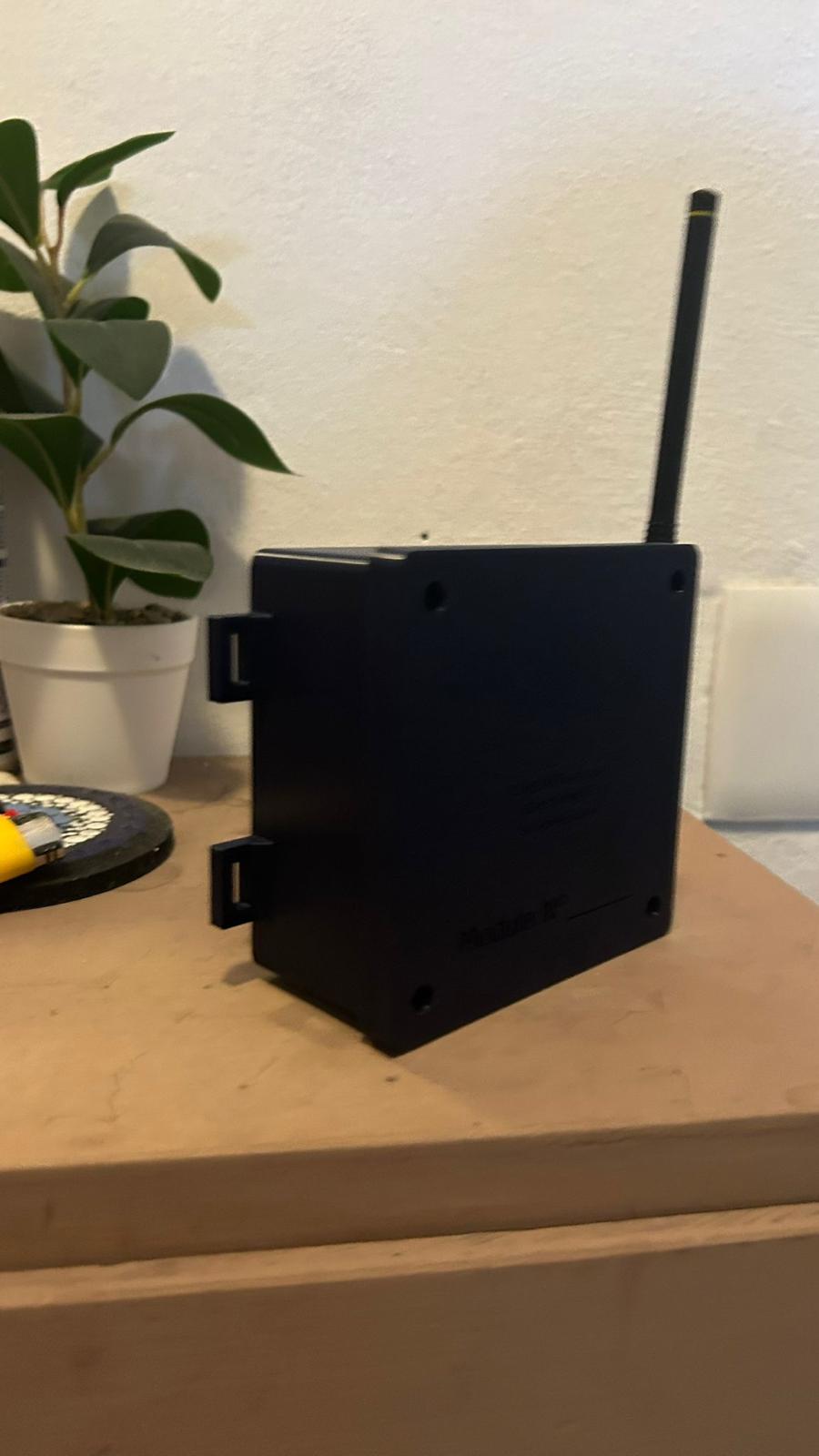
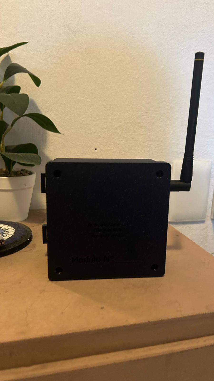
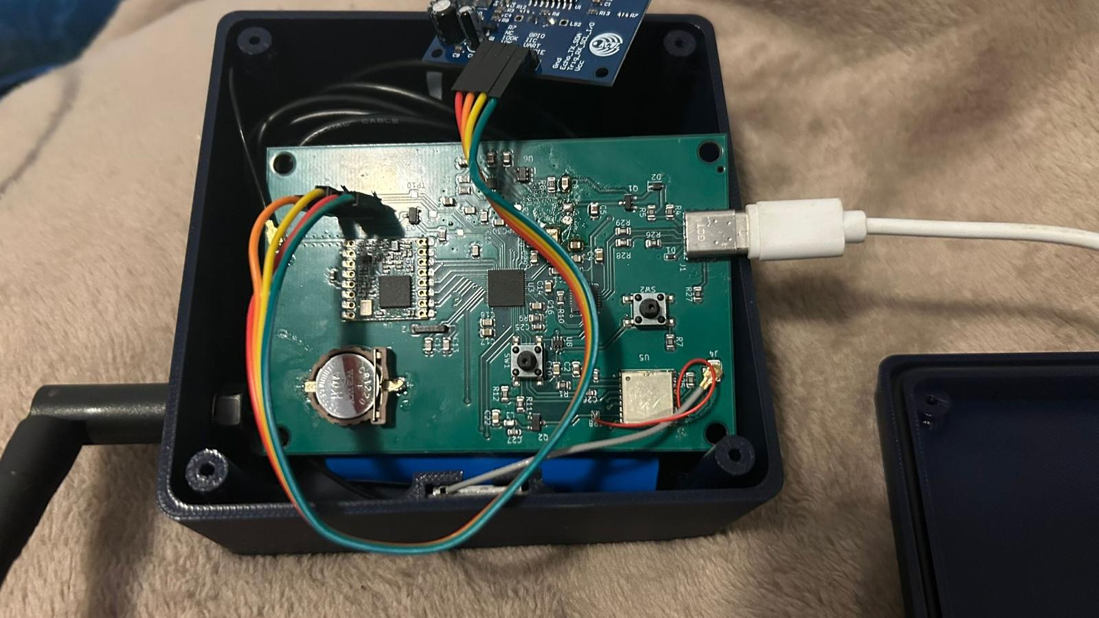
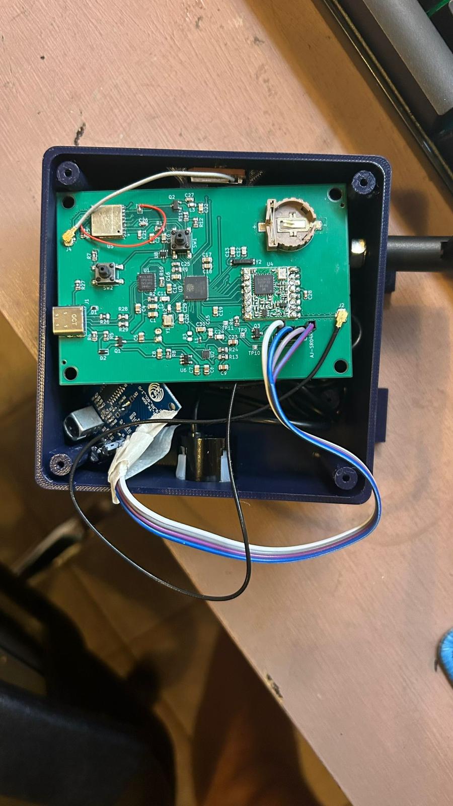
For example, Power management and USB to UART modules.
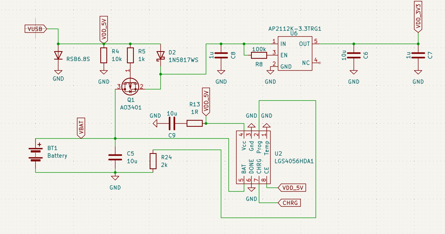
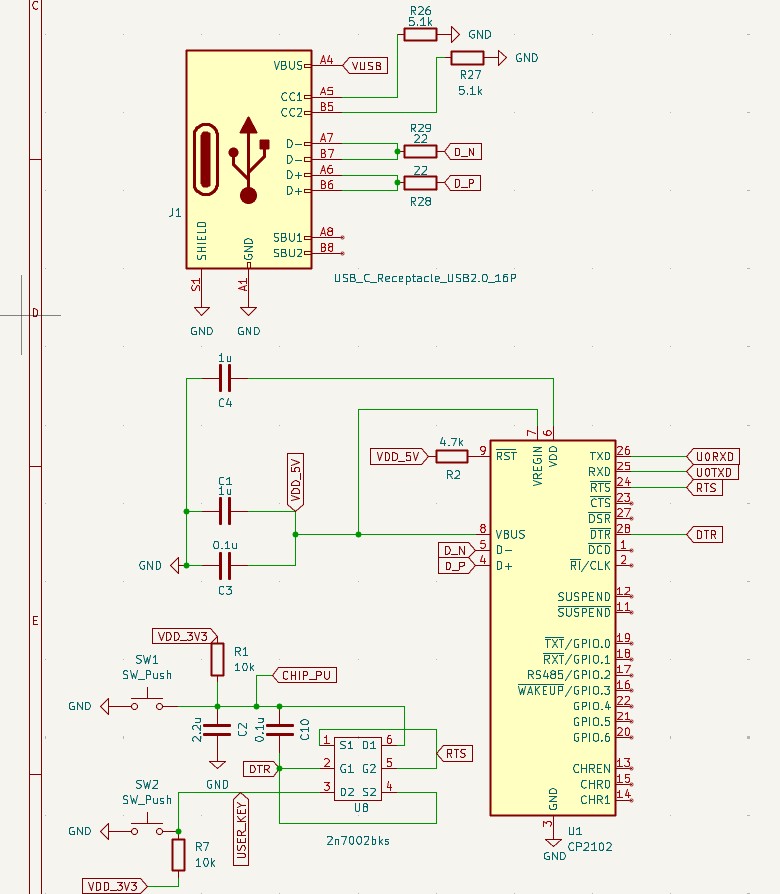

End-to-end IoT prototype for wireless telemetry using LoRa communication and GPS data acquisition, covering proof-of-concept validation, custom hardware development, embedded firmware, iterative PCB design, and a complete Node-RED data processing pipeline.
Codigo_lilygo/
Proof-of-concept implementation using a LilyGO T3 v1.6.1 development board. Used for early validation of LoRa communication and end-to-end data flow through an initial Node-RED pipeline before custom PCB and GPS integration.
Firmware/
Main embedded firmware for the custom PCB. Handles GPS acquisition, LoRa communication, and system logic.
Node Red/
Node-RED flows for telemetry ingestion, processing, and visualization.
Envolvente/
Mechanical enclosure design for system housing and protection.
V1.0/
First PCB iteration used to validate the custom LoRa hardware.
V2.0/
PCB redesign incorporating GPS integration and correcting initial hardware issues.
V3.0/
Final PCB revision with optimized layout and complete system integration.
.gitignore
Git ignore rules for build artifacts and temporary files.
README.md
Project documentation.
The project covers the complete development cycle of an embedded IoT system, including:
| Qty | Value | Footprint | References |
|---|---|---|---|
| 11 | 10k | Resistor_SMD:R_0402_1005Metric | R2, R3, R7, R13, R16, R17, R18, R19, R20, R25, R27 |
| 11 | TestPoint | TestPoint:TestPoint_Pad_1.0x1.0mm | TP1, TP2, TP3, TP4, TP5, TP6, TP7, TP8, TP9, TP10, TP11 |
| 5 | 0.1u | Capacitor_SMD:C_0402_1005Metric | C2, C3, C4, C6, C11 |
| 4 | 56pF | Capacitor_SMD:C_0603_1608Metric | C17, C18, C19, C20 |
| 3 | 100k | Resistor_SMD:R_0402_1005Metric | R1, R5, R24 |
| 3 | 100n | Capacitor_SMD:C_0402_1005Metric | C10, C12, C13 |
| 3 | 10u | Capacitor_SMD:C_0603_1608Metric | C1, C14, C15 |
| 2 | 1k | Resistor_SMD:R_0402_1005Metric | R23, R26 |
| 2 | 22 | Resistor_SMD:R_0402_1005Metric | R21, R22 |
| 2 | 5.1k | Resistor_SMD:R_0402_1005Metric | R11, R12 |
| 2 | Conn_Coaxial_Small | Connector_Coaxial:U.FL_Hirose_U.FL-R-SMT-1_Vertical | J1, J4 |
| 2 | LED | LED_SMD:LED_0603_1608Metric | D1, D2 |
| 2 | SS8050 | Package_TO_SOT_SMD:SOT-23 | Q2, Q4 |
| 1 | 1.13k | Resistor_SMD:R_0402_1005Metric | R9 |
| 1 | 1.18k | Resistor_SMD:R_0402_1005Metric | R8 |
| 1 | 1056TR | CR1220 socket:BAT_1056TR | BT1 |
| 1 | 10nF | Capacitor_SMD:C_0805_2012Metric | C16 |
| 1 | 1u | Capacitor_SMD:C_0402_1005Metric | C8 |
| 1 | 1u | Inductor_SMD:L_0805_2012Metric | L1 |
| 1 | 22.1k | Resistor_SMD:R_0402_1005Metric | R14 |
| 1 | 22u | Capacitor_SMD:C_0805_2012Metric | C7 |
| 1 | 27nH | Inductor_SMD:L_0805_2012Metric | L2 |
| 1 | 4.12k | Resistor_SMD:R_0402_1005Metric | R10 |
| 1 | 4.7u | Capacitor_SMD:C_0402_1005Metric | C9 |
| 1 | 4.7u | Capacitor_SMD:C_0603_1608Metric | C5 |
| 1 | 450k | Resistor_SMD:R_0402_1005Metric | R4 |
| 1 | 47.5k | Resistor_SMD:R_0402_1005Metric | R15 |
| 1 | 499k | Resistor_SMD:R_0402_1005Metric | R6 |
| 1 | AO3400A | Package_TO_SOT_SMD:SOT-23 | Q3 |
| 1 | AO3401A | Package_TO_SOT_SMD:SOT-23 | Q1 |
| 1 | BQ24074RGT | Package_DFN_QFN:VQFN-16-1EP_3x3mm_P0.5mm_EP1.6x1.6mm | U4 |
| 1 | Battery_Cell | Connector_JST:JST_EH_S2B-EH_1x02_P2.50mm_Horizontal | BT2 |
| 1 | CP2102N-Axx-xQFN24 | Package_DFN_QFN:QFN-24-1EP_4x4mm_P0.5mm_EP2.6x2.6mm | U6 |
| 1 | DebugLED | LED_SMD:LED_0603_1608Metric | D3 |
| 1 | ESP32-PICO-D4 | Package_DFN_QFN:QFN-48-1EP_7x7mm_P0.5mm_EP5.3x5.3mm | U1 |
| 1 | LOGO | logos:LogoUCU | UCU |
| 1 | RFM95W-915S2 | RF_Module:HOPERF_RFM9XW_SMD | U2 |
| 1 | SMBJ5.0A | Diode_SMD:D_SMB | CR1 |
| 1 | SW_Push | Button_Switch_SMD:SW_Push_1P1T_NO_CK_KMR2 | SW1 |
| 1 | SW_SPST | Button_Switch_THT:SW_E-Switch_EG1271_SPDT | SW2 |
| 1 | TESEO-LIV3R | Teseo:ARRAY_LIV3R_STM | U5 |
| 1 | TPS62A01ADRL | Package_TO_SOT_SMD:SOT-563 | U3 |
| 1 | U3 | Connector_PinSocket_1.00mm:PinSocket_1x04_P1.00mm_Vertical | AJ-SR04M1 |
| 1 | USBLC6-2P6 | Package_TO_SOT_SMD:SOT-666 | U7 |
| 1 | USB_C_Receptacle_USB2.0_16P | Connector_USB:USB_C_Receptacle_GCT_USB4085 | J2 |

pms67/HadesFCS
Complete flight control system designed from scratch. Hardware designed with KiCad.


Sierra-Lobo/mainboard-hardware
PyCubed mainboard v5 fork by Sierra Lobo for Foras Promineo CubeSat


lzptr/solar-controller
ESP32 Based PCB for Controlling a Solar System Light Chain


soerengraae/Vincent
An ESP32-based vinyl record scanner that looks up barcodes in the Discogs database and displays album information on a 3.97" e-ink screen. Still a work in progress.
It measures 80 × 50 mm and has 4 copper layers, 1.6 mm thick.
84 parts, built around the ESP32-PICO-D4, TESEO-LIV3R, TPS62A01ADRL and BQ24074RGTR. The full list of its parts is on this page, with links to each part's symbol and footprint where PCBKit's library has them.
From the ChrisKlein01/ArrozPCB repository on GitHub, at the commit this page was made from: the board is v2.0/PCB_LoRa+GPS.kicad_pcb and its schematic V1.0/PcbArroz.kicad_sch. PCBKit opens the board in the browser, with nothing to install.
Its repository states no licence, so its author keeps all rights: ask ChrisKlein01 before reusing the design.
