2 layers109 × 55 mm
Vbox fingers
CarVac/vbox
A rectangle controller for Melee with buttons arranged vertically instead of on a flat surface
20 parts6

 CarVac/vbox6
A rectangle controller for Melee with buttons arranged vertically instead of on a flat surface
Vbox mobo is an open-source printed circuit board by CarVac, from the CarVac/vbox repository on GitHub. It is a 2-layer board of 33.1 × 114.3 mm with 74 parts on 53 nets, routed with 714 tracks and 96 vias.
It is built around the RP2040, W25Q128JVSIQ and X05A26H12G, with the XC6206-2.8V among its other parts. Its parts include 35 resistors, 17 capacitors, 15 connectors, 4 ICs and 1 diode. It belongs with the RP2040 boards of this library.


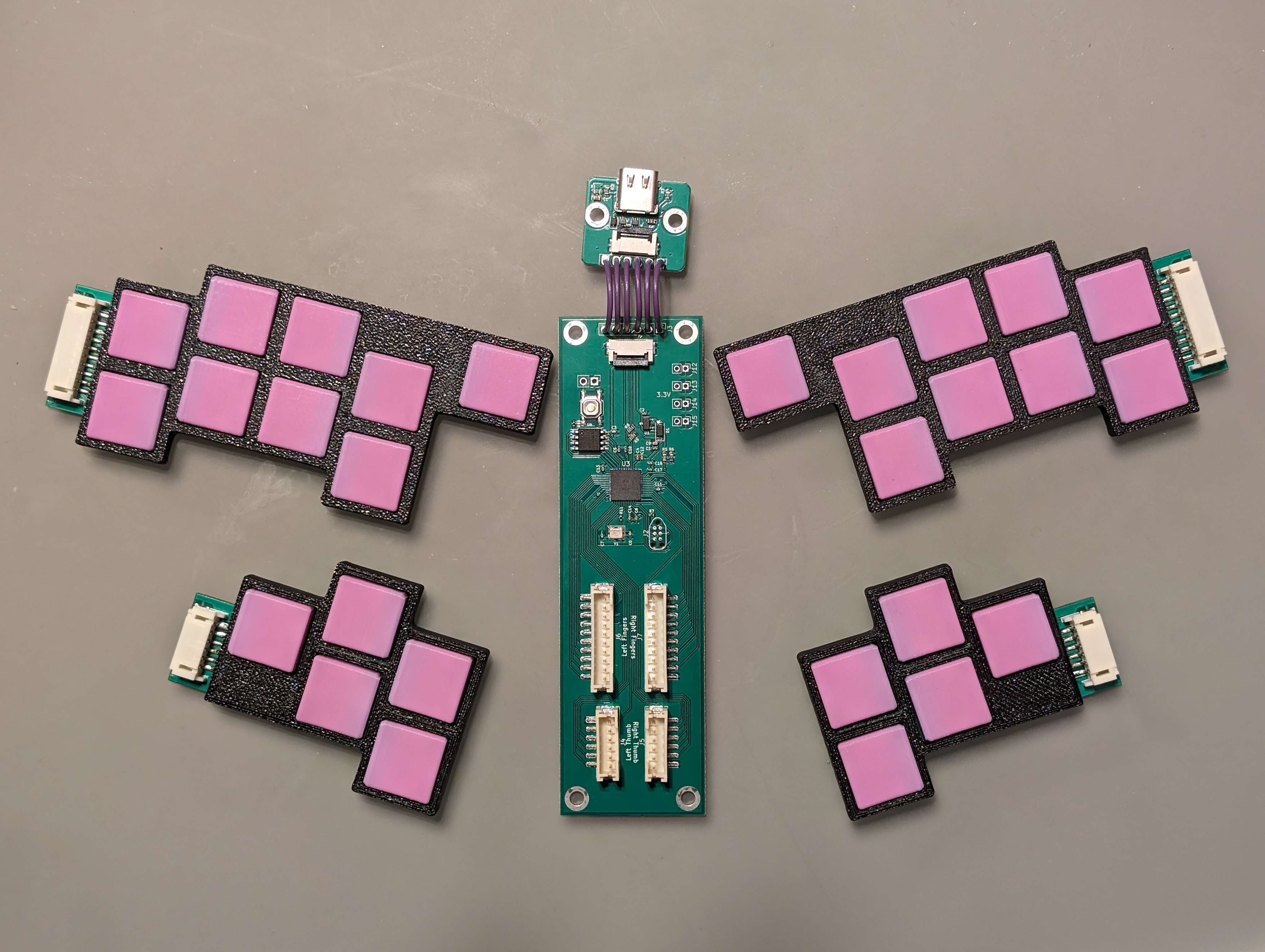
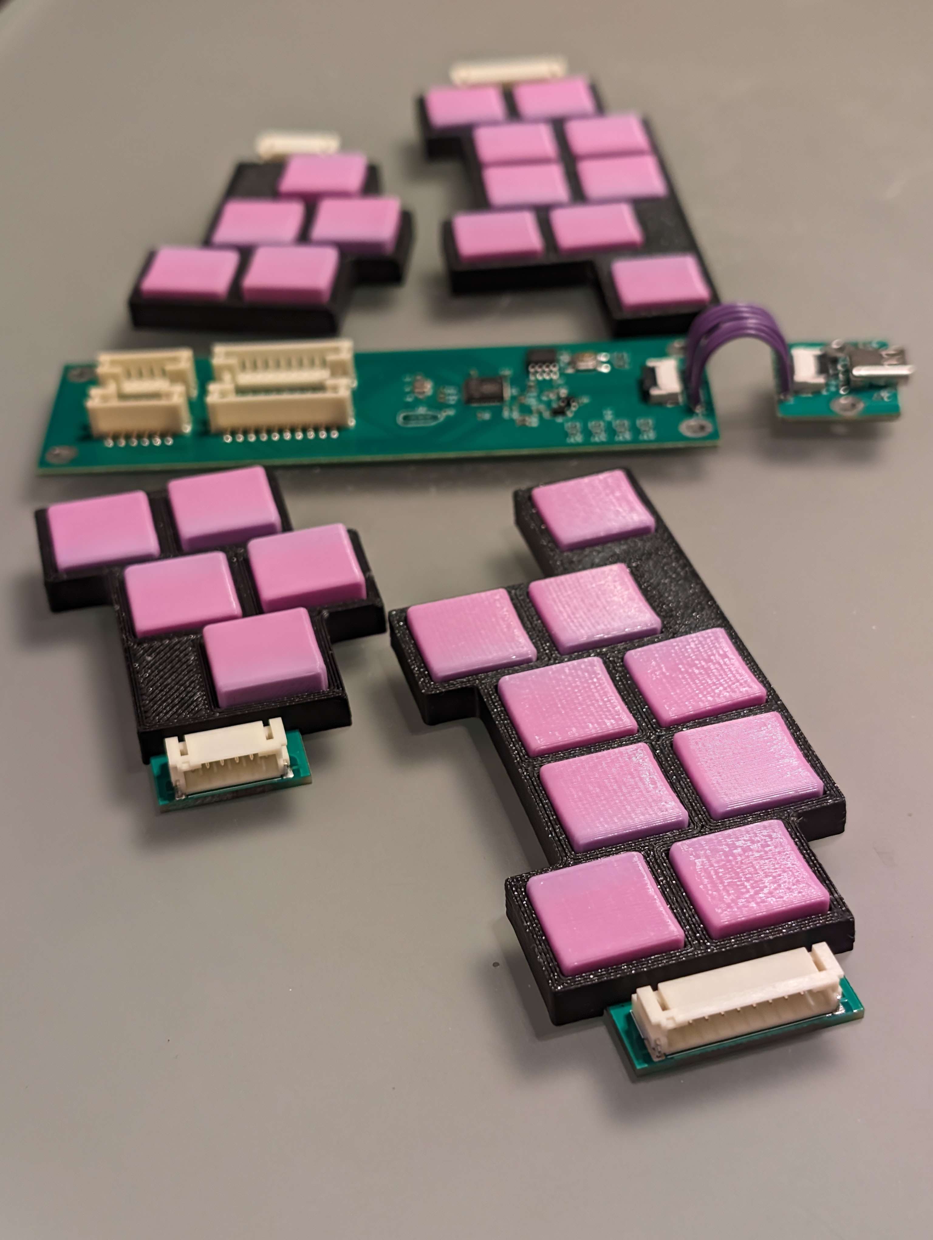
A rectangle controller for Melee with buttons arranged vertically instead of on a flat surface.
It's intended to be highly modular and configurable to fit different people's button layout preferences and hand sizes.
The left- and right-hand finger clusters and thumb clusters are mirror images of each other, with shared daughterboard PCBs, each side having single-sided layouts.
The switches used are Omron D2LS-21(20M), which are easy to hand-solder. The SMD JST PH connector was chosen for its low profile and ease of hand soldering.
Any switch location can be omitted if desired, and the housing printed with a blank where it would go.
The motherboard is designed to be as narrow as possible, with 4 JST connectors for button cluster daughterboards and one FFC connector for the USB-C breakout board.
It is derived from the Rana Labs Tadpole motherboard but with extremely heavy layout changes.
This project is licensed under the CERN Open Hardware License Version 2 - Strongly Reciprocal
This license:
If you are distributing vboxes or derivatives, you must provide a way for the recipient to access the source files (this repository or your fork if you modify it).
All of these files are posted as-is. This source is distributed WITHOUT ANY EXPRESS OR IMPLIED WARRANTY, INCLUDING OF MERCHANTABILITY, SATISFACTORY QUALITY, AND FITNESS FOR A PARTICULAR PURPOSE.
The housings may be customized to include or omit different button locations. Adjust the python file (which uses Build123D) where it says EDIT THESE TO REMOVE BUTTON HOLES and run the file to generate new STLs.
Print as many keycaps as necessary.
Housing TBD; there may be a non-folding version and a folding version.
You can use the motherboard with other finger clusters as long as you design them properly. The motherboard JST pinout is listed following, according to standard OpenFrame1 button locations.
You may use as many or as few buttons as you would like, but keep in mind that if you are intending this for melee you should at least populate the standard 20 OpenFrame1 buttons.
When the JSTs of the button clusters are mounted on the top side of the outer edges of the PCBs (as in the reference design) or the bottom side of the inner edges of the PCBs, the pinout should be the same as on the motherboard, and you must use "reversed" cable assemblies which map pin 1 to pin 1 and pin N to pin N.
When the JSTs of the button clusters are mounted on the bottom side of the outer edges of the PCBs or the top side of the inner edges of the PCBs, the pinout should be reversed relative to the motherboard (1 to 10 and 10 to 1 for the fingers, and 1 to 6 and 6 to 1 for the thumb clusters) and you must use "non-reversed" (they simply omit the word reversed) cable assemblies that connect pin 1 to pin N. The correct cable assemblies are listed below:
| Qty | Value | Footprint | References |
|---|---|---|---|
| 28 | 2k | Resistor_SMD:R_0402_1005Metric | R1, R2, R12, R13, R14, R15, R16, R17, R18, R19, R20, R21, R22, R23, R24, R25 +12 |
| 10 | 100nF | Capacitor_SMD:C_0402_1005Metric | C3, C5, C6, C11, C12, C13, C14, C15, C16, C17 |
| 4 | 1uF | Capacitor_SMD:C_0402_1005Metric | C1, C2, C4, C10 |
| 4 | Conn_01x01 | MountingHole:MountingHole_3.2mm_M3_ISO14580_Pad_TopBottom | J8, J9, J10, J11 |
| 4 | Conn_01x02 | Connector_PinHeader_2.00mm:PinHeader_1x02_P2.00mm_Vertical | J12, J13, J14, J15 |
| 2 | 1k | Resistor_SMD:R_0402_1005Metric | R10, R11 |
| 2 | 22pF | Capacitor_SMD:C_0402_1005Metric | C7, C8 |
| 2 | 27 | Resistor_SMD:R_0603_1608Metric | R8, R9 |
| 2 | Conn_01x06 | Connector_JST:JST_PH_B6B-PH-SM4-TB_1x06-1MP_P2.00mm_Vertical | J4, J5 |
| 2 | Conn_01x10 | Connector_JST:JST_PH_B10B-PH-SM4-TB_1x10-1MP_P2.00mm_Vertical | J6, J7 |
| 1 | 10k | Resistor_SMD:R_0402_1005Metric | R7 |
| 1 | 10k | Resistor_SMD:R_0603_1608Metric | R6 |
| 1 | 10uF | Capacitor_SMD:C_0402_1005Metric | C9 |
| 1 | 12MHz | Crystal:Crystal_SMD_3225-4Pin_3.2x2.5mm | Y1 |
| 1 | 5.6k | Resistor_SMD:R_0603_1608Metric | R5 |
| 1 | Boot | Button_Switch_SMD:SW_SPST_SKQG_WithStem | SW1 |
| 1 | Conn_01x02 | Connector_PinHeader_2.54mm:PinHeader_1x02_P2.54mm_Vertical | J1 |
| 1 | DuPont Connector | Connector_PinHeader_2.54mm:PinHeader_1x06_P2.54mm_Vertical | J3 |
| 1 | JTAG_TC2030 | PCM_marbastlib-various:CON_TC2030_outlined | J2 |
| 1 | RP2040 | qw-footprints:RP2040-QFN-56 | U3 |
| 1 | Schottky Diode | Diode_SMD:D_SOD-123 | D1 |
| 1 | W25Q128JVS | Package_SO:SOIC-8_5.3x5.3mm_P1.27mm | U4 |
| 1 | X05A26H12G | footprint:FPC-SMD_X05A26H12G | U2 |
| 1 | XC6206 | Package_TO_SOT_SMD:SOT-23 | U1 |
CarVac/vbox
A rectangle controller for Melee with buttons arranged vertically instead of on a flat surface

CarVac/vbox
A rectangle controller for Melee with buttons arranged vertically instead of on a flat surface

CarVac/vbox
A rectangle controller for Melee with buttons arranged vertically instead of on a flat surface

CarVac/vbox
A rectangle controller for Melee with buttons arranged vertically instead of on a flat surface

CarVac/vbox
A rectangle controller for Melee with buttons arranged vertically instead of on a flat surface

CarVac/vbox
A rectangle controller for Melee with buttons arranged vertically instead of on a flat surface

CarVac/vbox
A rectangle controller for Melee with buttons arranged vertically instead of on a flat surface

CarVac/vbox
A rectangle controller for Melee with buttons arranged vertically instead of on a flat surface

CarVac/vbox
A rectangle controller for Melee with buttons arranged vertically instead of on a flat surface

CarVac/vbox
A rectangle controller for Melee with buttons arranged vertically instead of on a flat surface

CarVac/vbox
A rectangle controller for Melee with buttons arranged vertically instead of on a flat surface

CarVac/vbox
A rectangle controller for Melee with buttons arranged vertically instead of on a flat surface


GRAMCTRL/GRAM-SLIM
Open source low-profile leverless design with an integrated RP2040.

quark-works/Integrated-OF1
Design files are available in this repository. Production files for JLCPCB in the releases page. Tested working and fitting previously mentioned Frame 1 cases.

GRAMCTRL/GRAM-PRISM
A modular and scalable design based on WunWae's Prism Controller

quark-works/OpenRectangleTemplate
RP2040 template for use with box style controllers for the GC
It measures 33.1 × 114.3 mm and has 2 copper layers, 1.6 mm thick.
74 parts, built around the RP2040, W25Q128JVSIQ, X05A26H12G and XC6206-2.8V. The full list of its parts is on this page, with links to each part's symbol and footprint where PCBKit's library has them.
From the CarVac/vbox repository on GitHub, at the commit this page was made from: the board is KiCad/mobo/Vbox_mobo.kicad_pcb and its schematic KiCad/fingers/Vbox_fingers.kicad_sch. PCBKit opens the board in the browser, with nothing to install.
Its repository states no licence, so its author keeps all rights: ask CarVac before reusing the design.