2 layers315.6 × 94 mm
 Bread80/CPC_Keyboards3
Keyboards for Amstrad CPC Computers
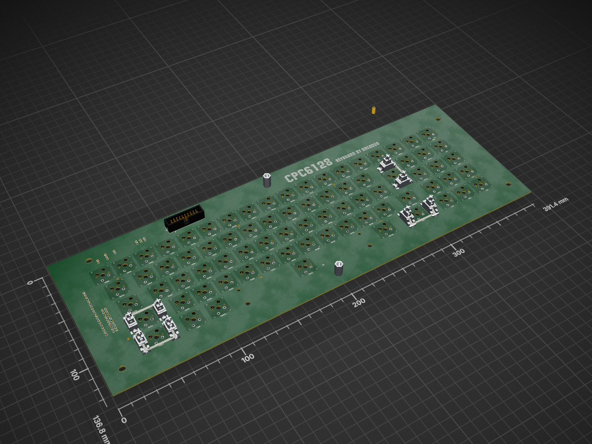
Keyboard is an open-source printed circuit board by Bread80, from the Bread80/CPC_Keyboards repository on GitHub, published under the CERN-OHL-P-2.0 licence. It is a 2-layer board of 391.4 × 136.8 mm with 181 parts on 103 nets, routed with 1,766 tracks and 82 vias.
Its parts include 76 diodes, 68 switches and 3 connectors. It belongs with the keyboards and input and retro computing and games boards of this library.
This project is a keyboard suitable for direct connection to an Amstrad CPC. The PCB uses tactile switches which can easily be labelled with suitable legends for the keytops. The current layout is that of an Amstrad CPC6128, but the key matrix is the same across all machines. The only differences are in the connector types and pinouts.
This board has connectors which are compatible with:
Plus machines: I'm not clear whether they use the same keyboard pinout or not. As such I can't say whether this board works with them or not.
Sadly it's not practical to add mounting holes suitable for mounting the keyboard on top of the CPC mainboard.
The repository includes an SVG file with key legend. This is suitable for the open source Inkscape software
74x Key switches[1]: Alps Apline SKHCBEA010. Mouser no: 688-SKHCBEA010 74x Keytops + Keycaps[2][3]: Alps Alpine SK2AA00090. Mouser: 688-SK2AA00090 'Standard pin header' (2.54mm spacing)[4] 2x Shunts[4] Connector(s) (to keyboard)[5] Connector(s) (to CPC)[6] Cable (keyboard to CPC)[7] 5x Standoffs, short)[8]: 13mm length, M3 x 0.5, 4.5mm OD, female/female. Mouser: M1260-3005-SS 5x Standoffs, long)[8]: 25mm, M3 x 0.5, 4.5mm OD, female/female. Mouser: 761-M1272-3005-SS 10x Screws[8]: M3 x 6mm. Mouser: 534-9191-3 --also-- key legend (printout)[9]
Mouser codes can be used at http://mouser.com [1] PCB will accept any generic 12mm 'tactile switch'. The specified model allows a keytop + keycap to be attched. This enables a printed key legend to be used. The same design is available engineered for 'operating force' values. In my tests this model had the best feel. [2] Other colours are available (for the keytops), product codes SK2AA000x0 where x is 6,7,8,9 (NOTE: other digits are different products!). [3] This product code includes both keycap and keytop. These are also available separately, but the combined pack is slightly cheaper. Consult the keyswitch data sheet for the full list of available options: https://www.mouser.co.uk/datasheet/2/15/SKHC-1370786.pdf
[4] For configuration jumpers. Source from ebay etc for sensible pricing. If you don't intend to change settings you can solder an offcut of wire instead. [5] Unless you need to attach multiple machines your best option here is to directly solder wire to the board. Otherwise pin header is probably the most convenient. You'll either need 1x20 or 2x10 depending on the machine, plus [6] Options here depend on your machine. The 20-pin inline connect machines will accept 'Dupont' style connectors, pin header etc. The 2x10 matrix connectors are more of a pin. I've successfully used FPC/FFC cable. With some patience this can be persuaded into the connector. These cables only seem to be available in very short lengths but ribbon (etc) cable can be soldered to the other end to run to the keyboard. Obviously some insulation will be helpful on the joins to prevent it shorting against anything (or each other)! You'll need 2x 10-pin cables, 571-FSN-21A-10 is a suitable Mouser product code. [7] Discreet cables or a length or ribbon cable is up to you. Not every line is connected but using a 20pin or 2x 10-pin ribbon cable saves you having to etsablish which aren't needed. Cable length is up to you but anything too short will make it difficult to position the keyboard where you want it. I'd suggest a /minimum/ of about eight inches (40cm). [8] I use standoffs as feet to lift to board of the desk and give space for the wiring underneath. You can give the keyboard some 'raking' by using longer ones at the rear. another option is to use a male/female standoff as an extender. The board is engineered for M3 screws/threads. Note: The PCB has three rows of mounting holes but the central row has not proved necessary and I'll remove them if I do an update. Just use the top and bottom rows. [9] Provided as an SVG suitable for Inkscape) in this here repository. If creating your own key legend, each key needs to be a maximum 10mm x 10mm
All the connectors are orientated in the same way as those on the Amstrad motherboard. I.e. the pin(s) towards the top of rear of the keyboard PCB are those towards the rear of the motherboard PCB and, for the the dual 10-pin connectors, the right-most connector on the keyboard PCB (when viewed from the top) connects to the right-most connector on the motherboard PCB.
Configuration is only needed if using the pair of 10-pin connectors to connect to the motherboard. If connecting to a CPC464, short (with a 'shunt') JP2 and the left-most two pins of JP1. If connecting to a CPC6128 short JP3 and the two right-most pins of JP1. Note that when connecting to a CPC464 JP3 should be left open, when connecting to a CPC6128 JP2 should be left open.
Keyboard legend files are in the 'legend' folder. The following designs/layouts are available. SVG files can be created, edited and printed with the open source Inkscape software. If you create anything new/interesting please contribute it back to the repository.
UK-CPC6128-with-464-colours.svg - Amstrad CPC6128 layout with UK legend using the colour scheme of an original Amstrad CPC464.
My aim with this project is to share something potentially useful with the community but I don't want to see my work being exploited for profit.
Therefore, it's okay to have a board manufactured for your own use and sell off the spare boards for an amount to cover your costs and postage. If you want to sell boards, or derivatives, for profit or as part of a business then talk to me first.
Website: https://bread80.com Github: https://github.com/Bread80 Mastodon: https://mstdn.social/@bread80 Twitter: https://twitter.com/bread80com
| Qty | Value | Footprint | References |
|---|---|---|---|
| 76 | 1N4148 | CPC_Keyswitch:D_SOD-123-Handsolder | D0, D1, D2, D10, D11, D12, D13, D14, D15, D16, D17, D18, D19, D20, D21, D22 +60 |
| 9 | MountingHole | MountingHole:MountingHole_2.2mm_M2_DIN965 | H7, H8, H9, H10, H11, H12, H13, H14, H15 |
| 4 | MountingHole | CPC_Keyswitch:MountingHole4.3mmx5.3mmNPTH | H1, H3, H4, H6 |
| 4 | Stabiliser 2u | Keyswitches:Stabilizer_MX_2u | H16, H17, H19, H20 |
| 2 | ENTER | Keyswitches:Kailh_socket_MX_optional | SW6, SW18 |
| 2 | Jumper_NC_Small | Connector_PinHeader_2.54mm:PinHeader_1x02_P2.54mm_Vertical | LK2, LK3 |
| 2 | MountingHole | MountingHole:MountingHole_4.3mm_M4_DIN965 | H2, H5 |
| 2 | SHIFT | Keyswitches:Kailh_socket_MX_optional | SW21, SW121 |
| 1 | , < | Keyswitches:Kailh_socket_MX_optional | SW39 |
| 1 | - = | Keyswitches:Kailh_socket_MX_optional | SW25 |
| 1 | . | Keyswitches:Kailh_socket_MX_optional | SW7 |
| 1 | . > | Keyswitches:Kailh_socket_MX_optional | SW31 |
| 1 | / ? | Keyswitches:Kailh_socket_MX_optional | SW30 |
| 1 | 0 | Keyswitches:Kailh_socket_MX_optional | SW15 |
| 1 | 0 _ | Keyswitches:Kailh_socket_MX_optional | SW32 |
| 1 | 1 | Keyswitches:Kailh_socket_MX_optional | SW13 |
| 1 | 1 ! | Keyswitches:Kailh_socket_MX_optional | SW64 |
| 1 | 2 | Keyswitches:Kailh_socket_MX_optional | SW14 |
| 1 | 2 " | Keyswitches:Kailh_socket_MX_optional | SW65 |
| 1 | 3 | Keyswitches:Kailh_socket_MX_optional | SW5 |
| 1 | 3 # | Keyswitches:Kailh_socket_MX_optional | SW57 |
| 1 | 4 | Keyswitches:Kailh_socket_MX_optional | SW20 |
| 1 | 4 $ | Keyswitches:Kailh_socket_MX_optional | SW56 |
| 1 | 5 | Keyswitches:Kailh_socket_MX_optional | SW12 |
| 1 | 5 % | Keyswitches:Kailh_socket_MX_optional | SW49 |
| 1 | 6 | Keyswitches:Kailh_socket_MX_optional | SW4 |
| 1 | 6 & | Keyswitches:Kailh_socket_MX_optional | SW48 |
| 1 | 7 | Keyswitches:Kailh_socket_MX_optional | SW10 |
| 1 | 7 ' | Keyswitches:Kailh_socket_MX_optional | SW41 |
| 1 | 8 | Keyswitches:Kailh_socket_MX_optional | SW11 |
| 1 | 8 ( | Keyswitches:Kailh_socket_MX_optional | SW40 |
| 1 | 9 | Keyswitches:Kailh_socket_MX_optional | SW3 |
| 1 | 9 ) | Keyswitches:Kailh_socket_MX_optional | SW33 |
| 1 | : * | Keyswitches:Kailh_socket_MX_optional | SW29 |
| 1 | ; + | Keyswitches:Kailh_socket_MX_optional | SW28 |
| 1 | @ | | Keyswitches:Kailh_socket_MX_optional | SW26 |
| 1 | A | Keyswitches:Kailh_socket_MX_optional | SW69 |
| 1 | B | Keyswitches:Kailh_socket_MX_optional | SW54 |
| 1 | C | Keyswitches:Kailh_socket_MX_optional | SW62 |
| 1 | CAPS | Keyswitches:Kailh_socket_MX_optional | SW70 |
| 1 | CLR | Keyswitches:Kailh_socket_MX_optional | SW16 |
| 1 | COMMON | Connector_PinHeader_2.54mm:PinHeader_1x02_P2.54mm_Vertical | LK6 |
| 1 | COPY | Keyswitches:Kailh_socket_MX_optional | SW9 |
| 1 | CPC Modular | Connector_IDC:IDC-Header_2x10_P2.54mm_Vertical | J2 |
| 1 | CTRL | Keyswitches:Kailh_socket_MX_optional | SW23 |
| 1 | Conn_01x19_Pin | Connector_PinHeader_2.54mm:PinHeader_1x19_P2.54mm_Vertical | J3 |
| 1 | D | Keyswitches:Kailh_socket_MX_optional | SW61 |
| 1 | DEL | Keyswitches:Kailh_socket_MX_optional | SW79 |
| 1 | DOWN | Keyswitches:Kailh_socket_MX_optional | SW2 |
| 1 | E | Keyswitches:Kailh_socket_MX_optional | SW58 |
| 1 | ESC | Keyswitches:Kailh_socket_MX_optional | SW66 |
| 1 | F | Keyswitches:Kailh_socket_MX_optional | SW53 |
| 1 | F1 | Connector_PinHeader_2.54mm:PinHeader_1x02_P2.54mm_Vertical | LK5 |
| 1 | F1 | Keyswitches:Kailh_socket_MX_optional | SW902 |
| 1 | F2 | Keyswitches:Kailh_socket_MX_optional | SW901 |
| 1 | F2 | Connector_PinHeader_2.54mm:PinHeader_1x02_P2.54mm_Vertical | LK4 |
| 1 | G | Keyswitches:Kailh_socket_MX_optional | SW52 |
| 1 | H | Keyswitches:Kailh_socket_MX_optional | SW44 |
| 1 | I | Keyswitches:Kailh_socket_MX_optional | SW35 |
| 1 | J | Keyswitches:Kailh_socket_MX_optional | SW45 |
| 1 | Jumper_3_Open | Connector_PinHeader_2.54mm:PinHeader_1x03_P2.54mm_Vertical | LK1 |
| 1 | K | Keyswitches:Kailh_socket_MX_optional | SW37 |
| 1 | L | Keyswitches:Kailh_socket_MX_optional | SW36 |
| 1 | LEFT | Keyswitches:Kailh_socket_MX_optional | SW8 |
| 1 | M | Keyswitches:Kailh_socket_MX_optional | SW38 |
| 1 | Membrane 464/6128 | Connector_PinHeader_2.54mm:PinHeader_2x10_P2.54mm_Vertical | J1 |
| 1 | N | Keyswitches:Kailh_socket_MX_optional | SW46 |
| 1 | O | Keyswitches:Kailh_socket_MX_optional | SW34 |
| 1 | P | Keyswitches:Kailh_socket_MX_optional | SW27 |
| 1 | Q | Keyswitches:Kailh_socket_MX_optional | SW67 |
| 1 | R | Keyswitches:Kailh_socket_MX_optional | SW50 |
| 1 | RIGHT | Keyswitches:Kailh_socket_MX_optional | SW1 |
| 1 | S | Keyswitches:Kailh_socket_MX_optional | SW60 |
| 1 | SPACE | Keyswitches:Kailh_socket_MX_optional | SW47 |
| 1 | Stabiliser 7u | CPC_Keyswitch:Stabilizer_MX_7u | H18 |
| 1 | T | Keyswitches:Kailh_socket_MX_optional | SW51 |
| 1 | TAB | Keyswitches:Kailh_socket_MX_optional | SW68 |
| 1 | U | Keyswitches:Kailh_socket_MX_optional | SW42 |
| 1 | UP | Keyswitches:Kailh_socket_MX_optional | SW0 |
| 1 | V | Keyswitches:Kailh_socket_MX_optional | SW55 |
The 173 most common of 181 parts.


ThisIsNotRocketScience/Eurorack-Modules
This is not Rocket Science presents: Eurorack modular synthesizer modules!


starlightk7/OpenKSK
Repository for Reproduction PCBs for Early 1990's Sony KSK Series Laser Boards, found in systems such as the Sega CD Model 1, 2 & Neo Geo CD Frontloader.

fwachsmuth/Synkino
Allows sound playback synchronised to a running,jittery Super 8 projector


It measures 391.4 × 136.8 mm and has 2 copper layers, 1.6 mm thick.
181 parts. The full list of its parts is on this page, with links to each part's symbol and footprint where PCBKit's library has them.
From the Bread80/CPC_Keyboards repository on GitHub, at the commit this page was made from: the board is Keyswitch_CPC6128_SMT/Keyboard.kicad_pcb and its schematic Keyswitch_CPC464_SMT/Keyboard.kicad_sch. PCBKit opens the board in the browser, with nothing to install.
Its repository publishes it under the CERN-OHL-P-2.0 licence: you may reuse it on that licence's terms (keep the author's notice, and for a copyleft licence share your changes alike).