2 layers179.8 × 116.7 mm

 BatteryTesterEngineering/Neware_RS485
Neware BTS4000 series battery cyclers RS485 communication protocol, reverse engineered
RS485 hardware is an open-source printed circuit board by BatteryTesterEngineering, from the BatteryTesterEngineering/Neware_RS485 repository on GitHub, published under the GPL-3.0 licence. It is a 2-layer board of 38 × 38 mm with 21 parts on 49 nets, routed with 188 tracks and 21 vias.
It is built around the SP3077EEN-L, FT232RNL and RJ45, with the EG2211 and EG6201 among its other parts. Its parts include 6 resistors, 4 capacitors, 2 ICs, 2 diodes and 2 connectors. It belongs with the interfaces and adapters boards of this library.


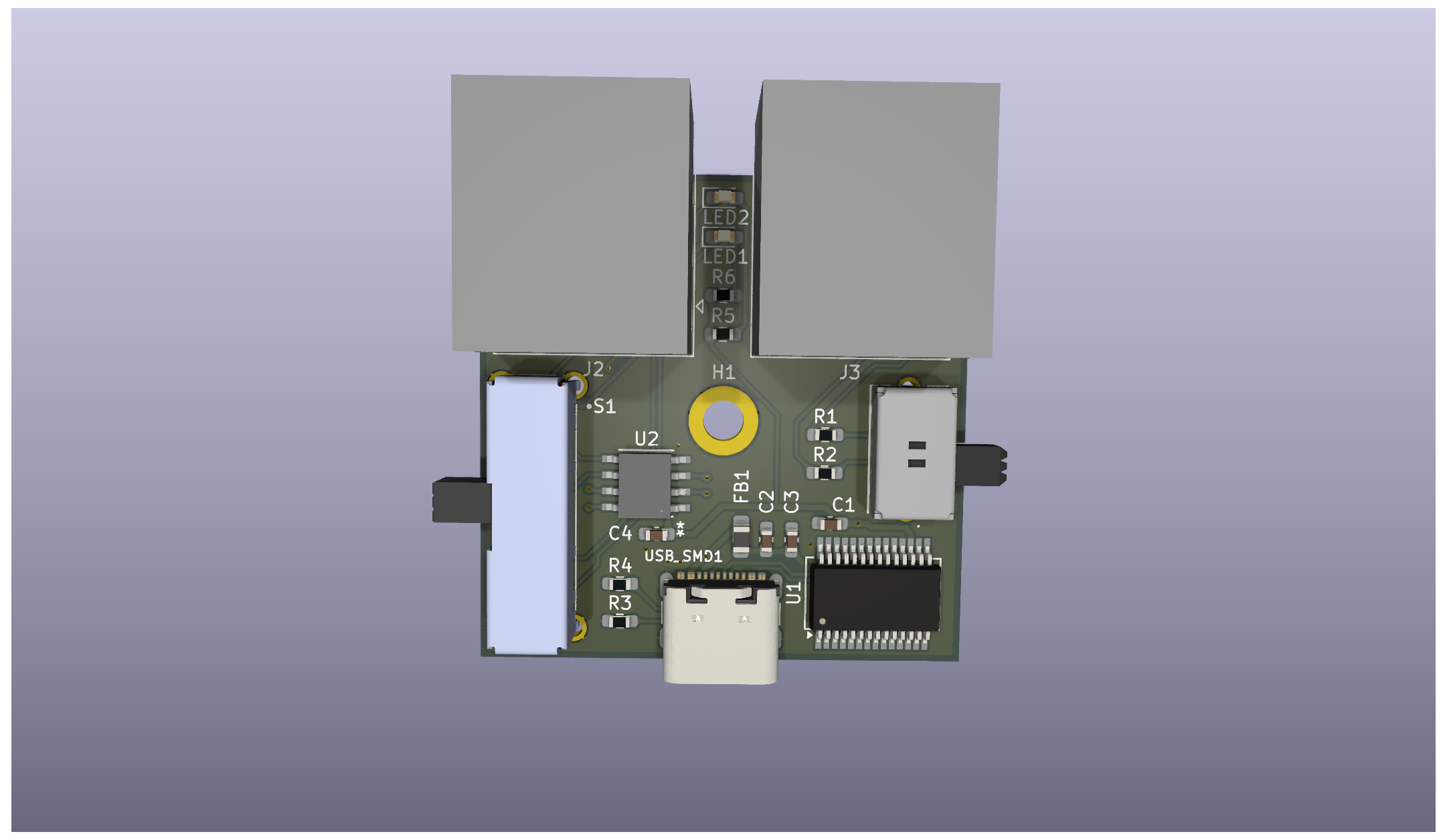
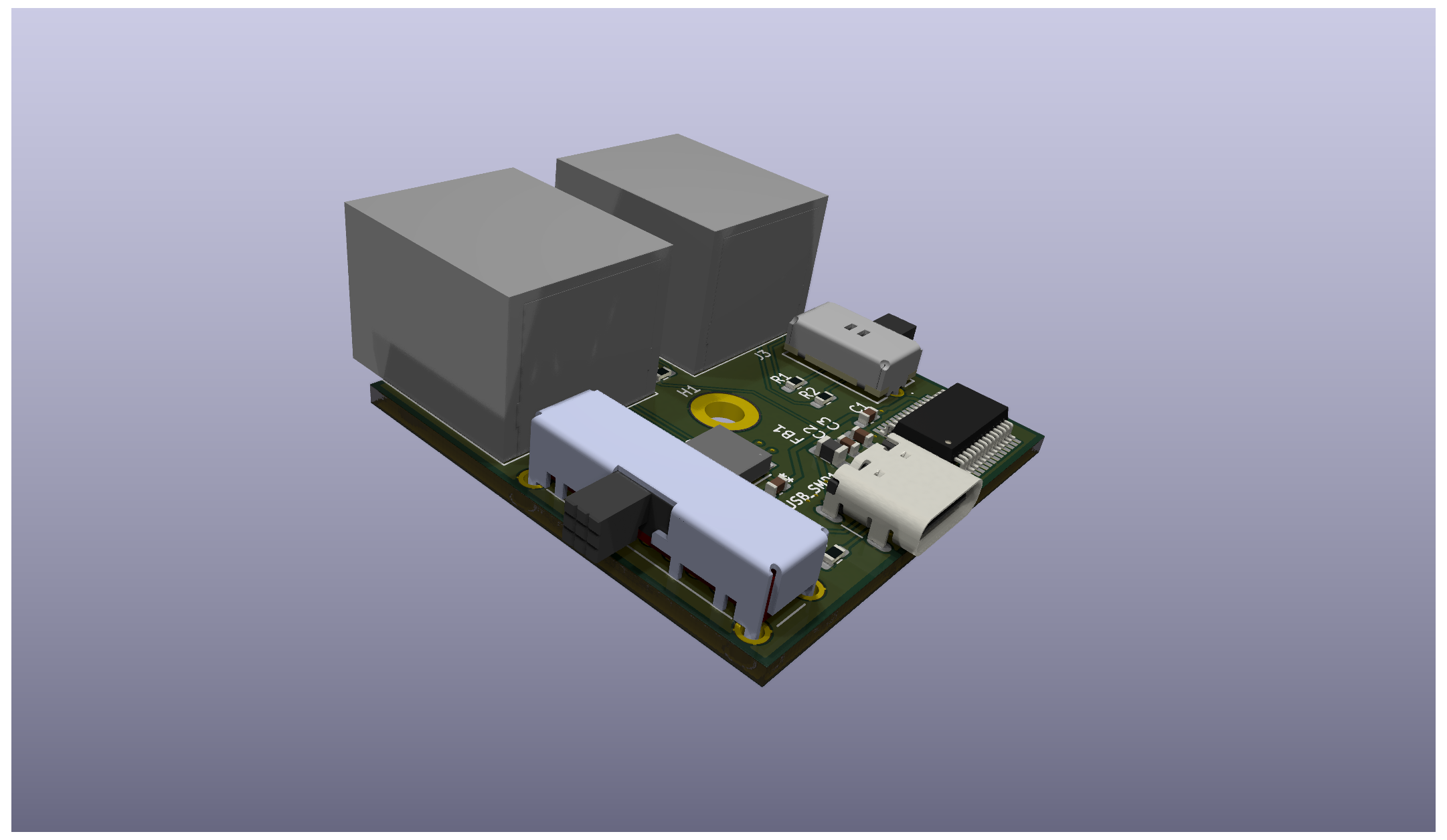
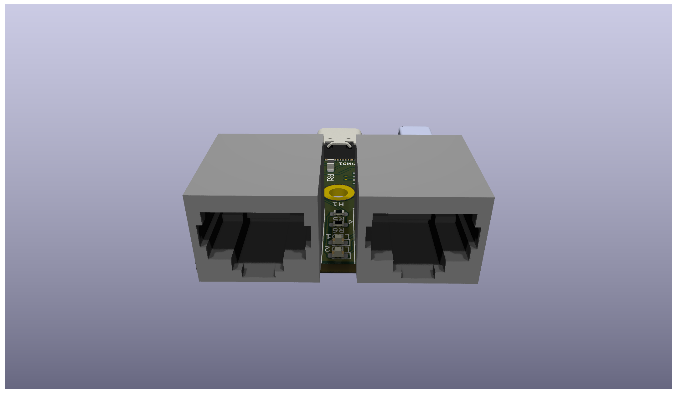
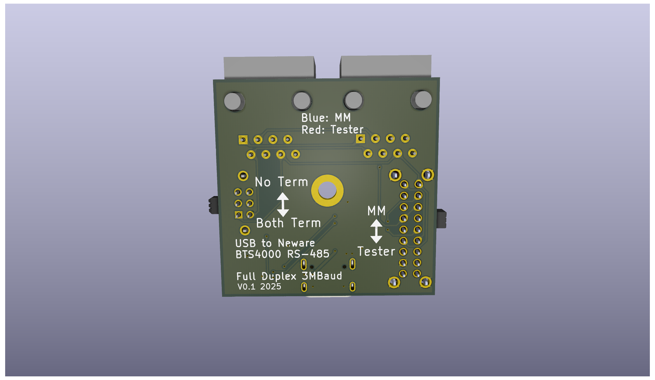
This is the Kicad project and output files for a USB Adapter that allows any computer to listen and transmit on the Neware BTS4000 RS485 bus. The adapter is based on the FTDI FT232RN chip, which includes drivers for all major operating systems. The transciever is a MaxLinear SP3077E, which allows for full duplex 3MBaud communication.
The bus connectors are intended to duplicate the RS485 bus connections on a Middle Machine or Battery Tester. There are 2 RJ45 Jacks which are wired in parallel, allowing the device to be used in the same daisy-chain fashion as a Neware device.
The adapter includes 2 slide switches.
Toggles the adapter between "Middle Machine Mode" and "Tester Mode". Since the RS485 bus is a full duplex bus, it matters which line the adapter is receiving on, and which it is transmitting on. With the switch slid towards the RJ45 jacks, the adapter acts as a middle machine, receiving on the same line that battery testers are transmitting on, and transmitting on the line that battery testers are receiving on. With the switch slid towards the USB-C jack, the adapter acts as tester, receiving from the middle machine and transmitting to the middle machine.
| Switch Position | Adapter Mode | Adapter TX | Adapter RX | LED Color |
|---|---|---|---|---|
| Towards RJ45 | Middle Machine | Middle Machine TX | Middle Machine RX | Blue |
| Towards USB-C | Tester | Middle Machine RX | Middle Machine TX | Red |
Toggles the RS485 Termination Resistors on or off. With the switch slid towards the RJ45 jacks, there are no termination resistors on the bus. With the switch slid towards the USB-C jack, the adapter terminates the TX and RX busses with a 120Ω resistor on each bus. Whether or not you need the termination resistors enabled dependes on the length of the bus and what other devices are on the bus. A typical RS485 bus has a temination resistor enabled on both physical ends of the bus.
The connection to a computer is a USB-C connector configured to run at USB 2.0 speeds. The USB connector has 5.1kΩ resistors on the CC lines, which allow it to work with USB C<->C cables or USB A<->C cables.
The outputs/manufacturing_files subfolder contains gerber and OBD files needed for PCB manufacturing, as well as the BOM file. The BOM contains manufacturer and part number data for digikey and LCSC to make sourcing parts easy regardless of where the boards are manufactured.
All passives are 0603 or larger, with the large-pad footprints chosen to allow for hand soldering. Similarly, the pitch of all components should be large enough for hand soldering.
| Qty | Value | Footprint | References |
|---|---|---|---|
| 2 | 100nF | Capacitor_SMD:C_0603_1608Metric_Pad1.08x0.95mm_HandSolder | C1, C4 |
| 2 | 120 | Resistor_SMD:R_0603_1608Metric_Pad0.98x0.95mm_HandSolder | R1, R2 |
| 2 | 5100 | Resistor_SMD:R_0603_1608Metric_Pad0.98x0.95mm_HandSolder | R3, R4 |
| 2 | RJ45 | Connector_RJ:RJ45_Amphenol_54602-x08_Horizontal | J2, J3 |
| 1 | 100 | Resistor_SMD:R_0603_1608Metric_Pad0.98x0.95mm_HandSolder | R5 |
| 1 | 10nF | Capacitor_SMD:C_0603_1608Metric_Pad1.08x0.95mm_HandSolder | C3 |
| 1 | 270 | Resistor_SMD:R_0603_1608Metric_Pad0.98x0.95mm_HandSolder | R6 |
| 1 | 4.7uF | Capacitor_SMD:C_0603_1608Metric_Pad1.08x0.95mm_HandSolder | C2 |
| 1 | BLUE_LED | LED_SMD:LED_0603_1608Metric_Pad1.05x0.95mm_HandSolder | LED2 |
| 1 | EG2211 | EG2211:EG2211 | S2 |
| 1 | EG6201 | EG6201:SW_EG6201 | S1 |
| 1 | FT232RNL | Package_SO:SSOP-28_5.3x10.2mm_P0.65mm | U1 |
| 1 | FerriteBead | Inductor_SMD:L_0805_2012Metric_Pad1.05x1.20mm_HandSolder | FB1 |
| 1 | MountingHole_Pad | MountingHole:MountingHole_3.2mm_M3_DIN965_Pad | H1 |
| 1 | RED_LED | LED_SMD:LED_0603_1608Metric_Pad1.05x0.95mm_HandSolder | LED1 |
| 1 | SP3077EEN-L | SP3077EEN_L:SOIC8_3P99X4P98 | U2 |
| 1 | USB_C_Receptacle_USB2.0_16P | Connector_USB:USB_C_Receptacle_GCT_USB4105-xx-A_16P_TopMnt_Horizontal | USB_SMD1 |


pipipipi2002/stm32f446vetx-dev-module
Dev Module for STM32F446VETx


ATK-1/SeniorDesign_SwanGanz
The contributors to this senior design project were Nathan DeLaRosa, Ashton Knecht, Jack Son, and Jerry Xia under the supervision of Dr. Jonathan Valvano.

Kenneth-Goveas/CARL-Air-Brake-Power-Supply-Hardware
This repository contains the electronic hardware design for the power supply module of the [CARL Air Brake][cab-repo] computer.


RealtimeRoboticsGroup/electrical
This project is open-source hardware and is licensed under the Solderpad Hardware License v2.1 (the "License"), which is a permissive license based on the Apache License, Version 2.0.
It measures 38 × 38 mm and has 2 copper layers, 1.6 mm thick.
21 parts, built around the SP3077EEN-L, FT232RNL, RJ45 and EG2211. The full list of its parts is on this page, with links to each part's symbol and footprint where PCBKit's library has them.
From the BatteryTesterEngineering/Neware_RS485 repository on GitHub, at the commit this page was made from: the board is RS485_hardware/RS485_hardware.kicad_pcb and its schematic RS485_hardware/RS485_hardware.kicad_sch. PCBKit opens the board in the browser, with nothing to install.
Its repository publishes it under the GPL-3.0 licence: you may reuse it on that licence's terms (keep the author's notice, and for a copyleft licence share your changes alike).