4 layers75 × 70 mm
Small Pendant
mjhaahr/RGB-LED-Pendant
Small RGB LED Pendant using 1010 (1.0x1.0mm) WS2812B LEDs powered by an ESP32-C3 Mini with a BNO055 IMU
260 parts2MIT

 Batterhead221/port_sprite
Compact USB-C to UART debug/programming interface for embedded hardware projects.
Port sprite is an open-source printed circuit board by Batterhead221, from the Batterhead221/port_sprite repository on GitHub. It is a 4-layer board of 51.6 × 37.8 mm with 34 parts on 31 nets, routed with 287 tracks and 92 vias.
It is built around the AP2112K-3.3 and TPD2EUSB30DRT. Its parts include 8 resistors, 6 capacitors, 3 ICs, 3 diodes and 3 switches. It belongs with the interfaces and adapters boards of this library.


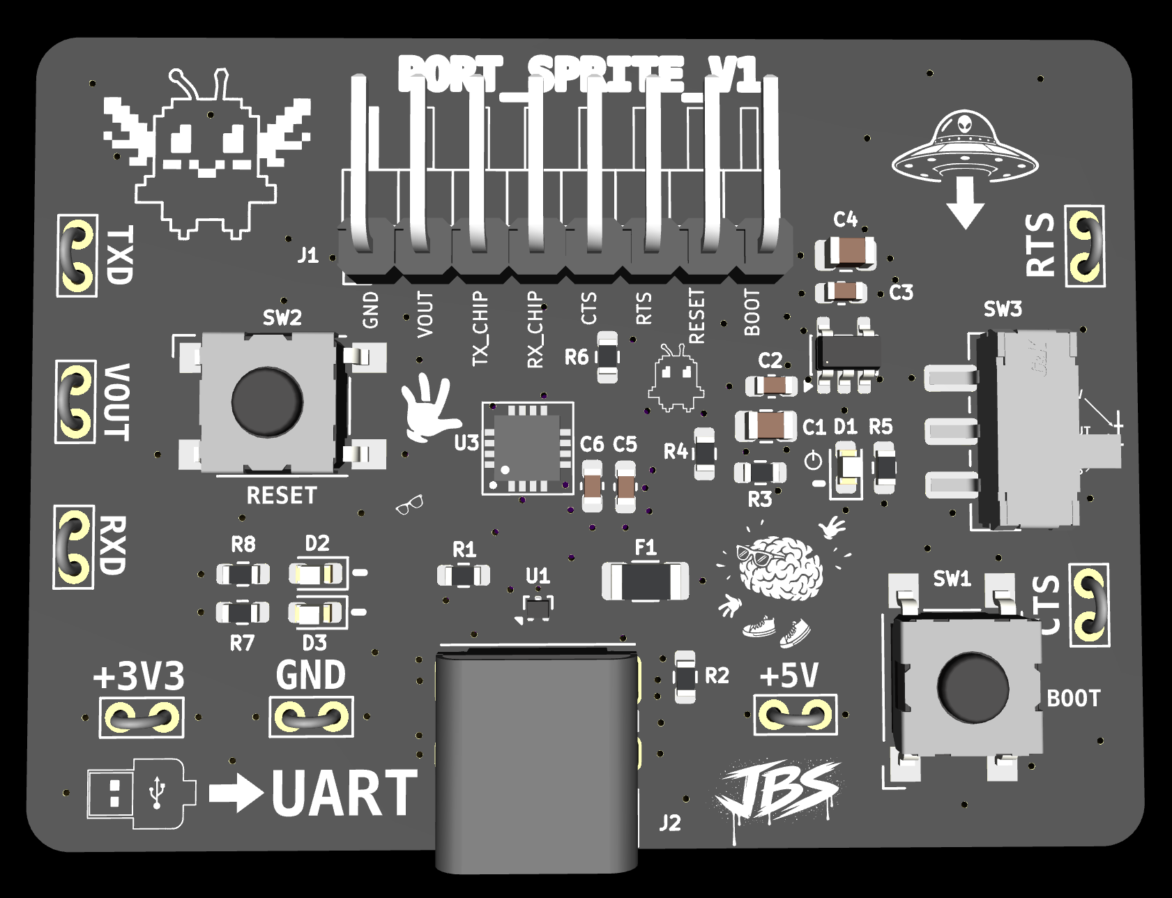
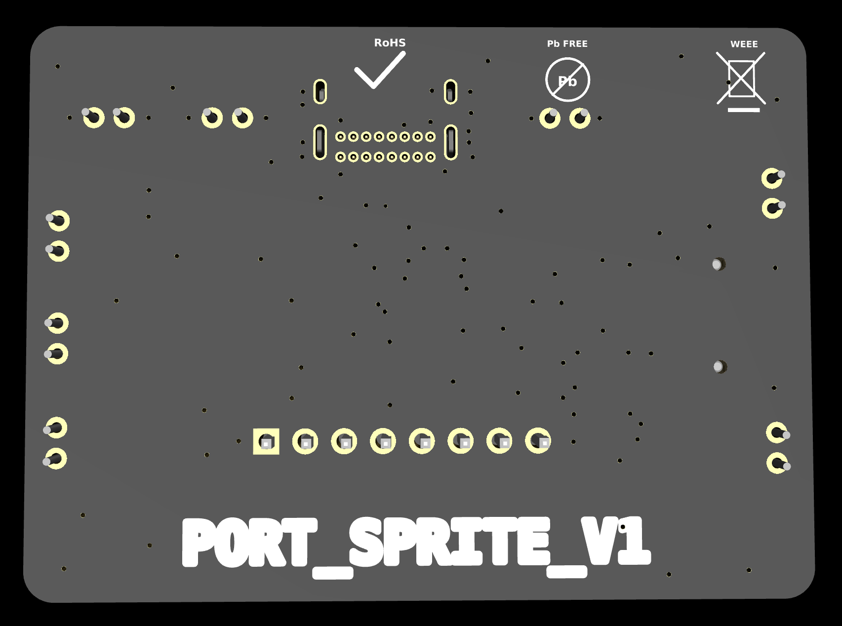
Compact USB-C to UART debug/programming interface for embedded hardware projects.
PORT_SPRITE is a reusable bench tool for custom PCB bring-up. It provides USB-C serial access, 3.3V UART logic, selectable target power output, activity LEDs, reset/boot controls, and labeled test points so new boards can be programmed, tested, and debugged without rebuilding the same support circuit every time.
USB in. UART out. Tiny port familiar doing serial errands.
| Item | Value |
|---|---|
| Revision | V1 |
| Status | In layout / pre-fabrication review |
| EDA | KiCad |
| Board type | USB-C to UART debug interface |
Computer / USB-C
        ↓ USB 2.0
PORT_SPRITE / CP2102N
        ↓ UART / reset / boot / VOUT
Target microcontroller board
PORT_SPRITE is not the target application board. It is a reusable debug/programming helper for other embedded projects.
PORT_SPRITE is meant to live on the bench and plug into future embedded projects.
Use it for:
| Item | Value |
|---|---|
| USB-UART bridge | CP2102N-Axx-xQFN20 |
| USB connector | USB-C USB 2.0 receptacle |
| UART logic level | 3.3V |
| Target power output | Selectable 3.3V or fused USB 5V |
| Regulator | AP2112K-3.3 |
| USB ESD | TPD2EUSB30 or equivalent |
| Target header | 1x8 UART/debug header |
| Manual controls | RESET and BOOT_LOW buttons |
| Indicators | Power LED, TX LED, RX LED |
| Board role | USB-C UART/debug/programming helper |
The UART signal pins use 3.3V logic.
The VOUT selector can provide either 3.3V or 5V power to the target, but the UART logic does not become 5V logic.
UART TX/RX/CTS/RTS logic level = 3.3V
VOUT selectable rail            = 3.3V or 5V
Do not connect PORT_SPRITE UART pins directly to a target that drives 5V logic unless level shifting or 5V tolerance is confirmed.
The slide switch selects what voltage appears on the VOUT pin.
| Switch input | Source |
|---|---|
+3V3 | AP2112K 3.3V regulator output |
VBUS_5V | Fused USB 5V rail |
VOUT is intended for small target boards only. Do not use it as a high-current supply.
BOOT_LOW is a pull-low boot control intended for ESP-style boot/GPIO0 workflows.
For STM32-style BOOT0, confirm the target board requirements before use. STM32 BOOT0 often expects pull-high behavior instead.
| Pin | Signal | Direction / Purpose |
|---|---|---|
| 1 | GND | Ground reference |
| 2 | VOUT | Selected target power output |
| 3 | TXD_TO_TARGET_RX | PORT_SPRITE TXD to target RX |
| 4 | RXD_FROM_TARGET_TX | Target TX to PORT_SPRITE RXD |
| 5 | CTS | CP2102N CTS |
| 6 | RTS | CP2102N RTS |
| 7 | RESET | Target reset, button pulls low |
| 8 | BOOT_LOW | Target boot/GPIO0, button pulls low |
UART wiring crosses TX and RX:
PORT_SPRITE TXD_TO_TARGET_RX  → target RX
PORT_SPRITE RXD_FROM_TARGET_TX ← target TX
PORT_SPRITE GND               ↔ target GND
PORT_SPRITE VOUT              → optional target power input
RESET and BOOT_LOW are optional and depend on the target board design.
| Test Point | Net | Purpose |
|---|---|---|
| TP1 | GND | Ground reference |
| TP2 | VBUS_5V | USB 5V rail check |
| TP3 | +3V3 | 3.3V regulator output check |
| TP4 | RXD_FROM_TARGET_TX | UART RX probe point |
| TP5 | TXD_TO_TARGET_RX | UART TX probe point |
| TP6 | CTS | Flow-control probe point |
| TP7 | RTS | Flow-control / control probe point |
| TP8 | VOUT | Selected target output voltage |
| Ref | Part | Notes |
|---|---|---|
| U1 | CP2102N-Axx-xQFN20 | USB-to-UART bridge |
| U2 | TPD2EUSB30 or equivalent | USB D+/D- ESD protection |
| U3 | AP2112K-3.3 | 3.3V LDO regulator |
| J1 | USB-C USB 2.0 receptacle | Device/sink input |
| J2 | 1x8 target debug header | UART/debug interface |
| SW1 | SPDT slide switch | Selects VOUT source |
| SW2 | RESET button | Pulls target RESET low |
| SW3 | BOOT button | Pulls BOOT_LOW low |
USB-C VBUS
      ↓
fuse / protection
      ↓
VBUS_5V rail
      ↓
AP2112K-3.3 regulator → +3V3
      ↓
VOUT selector chooses +3V3 or VBUS_5V
      ↓
target VOUT pinBefore plugging into a computer:
VBUS_5V is not shorted to GND.+3V3 is not shorted to GND.VOUT is not shorted to GND.Power checks:
VBUS_5V.+3V3.VOUT in both positions.USB checks:
Connect:
TXD_TO_TARGET_RX ↔ RXD_FROM_TARGET_TXOpen a serial terminal. Any typed characters should echo back.
Suggested settings:
Baud: 115200
Data: 8
Parity: none
Stop: 1
Flow control: nonePotential V2 ideas:
Expected image paths for GitHub README rendering:
Outputs/
  IMG/
    3D-T.png
    3D-B.png
    SCHEMATIC.png
    L1-SIG.png
L2-GND.pngPORT_SPRITE is a low-voltage debug/helper PCB. Verify UART voltage levels, shared ground, selected VOUT voltage, and target pin direction before connecting it to another project.
Designed & engineered by Brandon Shelly
| Qty | Value | Footprint | References |
|---|---|---|---|
| 3 | 100NF | CAPS:C_0603_1608Metric | C2, C3, C6 |
| 3 | 1K | RESISTOR:R_0603 | R5, R7, R8 |
| 2 | 10U | CAPS:C_0805_2012Metric | C1, C4 |
| 2 | 5.1K | RESISTOR:R_0603 | R1, R2 |
| 1 | +3V3 | TEST_POINT:TestPoint_Bridge_Pitch2.0mm_Drill0.7mm | TP6 |
| 1 | +5V | TEST_POINT:TestPoint_Bridge_Pitch2.0mm_Drill0.7mm | TP7 |
| 1 | 10K | RESISTOR:R_0603 | R6 |
| 1 | 1U | CAPS:C_0603_1608Metric | C5 |
| 1 | 22.1K | RESISTOR:R_0603 | R3 |
| 1 | 47.5K | RESISTOR:R_0603 | R4 |
| 1 | 500mA | FUSE:Fuse_1206_3216Metric | F1 |
| 1 | AP2112K-3.3 | SOT:SOT-23-5 | U2 |
| 1 | BOOT_LOW_BTN | ON/OFF:SW_SPST_Omron_B3FS-100xP | SW1 |
| 1 | CP2102N-Axx-xQFN20 | USB_TO_UART:WFQFN-20 | U3 |
| 1 | CTS | TEST_POINT:TestPoint_Bridge_Pitch2.0mm_Drill0.7mm | TP3 |
| 1 | GND | TEST_POINT:TestPoint_Bridge_Pitch2.0mm_Drill0.7mm | TP8 |
| 1 | PWR (RED) | LED:LED_0603_1608Metric | D1 |
| 1 | RESET_BTN | ON/OFF:SW_SPST_Omron_B3FS-100xP | SW2 |
| 1 | RTS | TEST_POINT:TestPoint_Bridge_Pitch2.0mm_Drill0.7mm | TP2 |
| 1 | RX (BLUE) | LED:LED_0603_1608Metric | D2 |
| 1 | RXD | TEST_POINT:TestPoint_Bridge_Pitch2.0mm_Drill0.7mm | TP5 |
| 1 | SLIDE_SWITCH | ON/OFF:SW_SPDT_CK_JS102011SAQN | SW3 |
| 1 | TPD2EUSB30 | SOT:Texas_DRT-3 | U1 |
| 1 | TX (YELLOW) | LED:LED_0603_1608Metric | D3 |
| 1 | TXD | TEST_POINT:TestPoint_Bridge_Pitch2.0mm_Drill0.7mm | TP4 |
| 1 | UART_TARGET_HEADER | PIN_HEADER:PinHeader_1x08_P2.54mm_Horizontal | J1 |
| 1 | USB_C_Receptacle_USB2.0_14P | USB:USB_C_Receptacle_GCT_USB4085 | J2 |
| 1 | VOUT | TEST_POINT:TestPoint_Bridge_Pitch2.0mm_Drill0.7mm | TP1 |
mjhaahr/RGB-LED-Pendant
Small RGB LED Pendant using 1010 (1.0x1.0mm) WS2812B LEDs powered by an ESP32-C3 Mini with a BNO055 IMU

davidfobar/CelestialSync
This an telescope mount controller inspired by OnStep and OpenAstroTracker, but written OOP to be maintainable.


qiaoyo/TellMeLight
TellMeLight is designed for ai hardware full-lifetime cycle.
o7-machinehum/phantomdrive
Seemingly normal USB drive with a hidden security feature


jkiv/cm4-carriers
KiCad design files for various Raspberry Pi Compute Module 4 (CM4) carrier boards.

udu3324/stm32pe-midi
a midi controller using the mpe protocol to create more expressive music
It measures 51.6 × 37.8 mm and has 4 copper layers, 1.6 mm thick.
34 parts, built around the AP2112K-3.3 and TPD2EUSB30DRT. The full list of its parts is on this page, with links to each part's symbol and footprint where PCBKit's library has them.
From the Batterhead221/port_sprite repository on GitHub, at the commit this page was made from: the board is ECAD/PORT_SPRITE.kicad_pcb and its schematic ECAD/PORT_SPRITE.kicad_sch. PCBKit opens the board in the browser, with nothing to install.
Its repository states no licence, so its author keeps all rights: ask Batterhead221 before reusing the design.