


2 layers53.2 × 53.5 mm
BRUSHLESS
AssaadMH/sensorless-bldc-control
Spinning a brushless motor with no position sensor — commutating on the back-EMF zero crossings instead.
14 parts1MIT
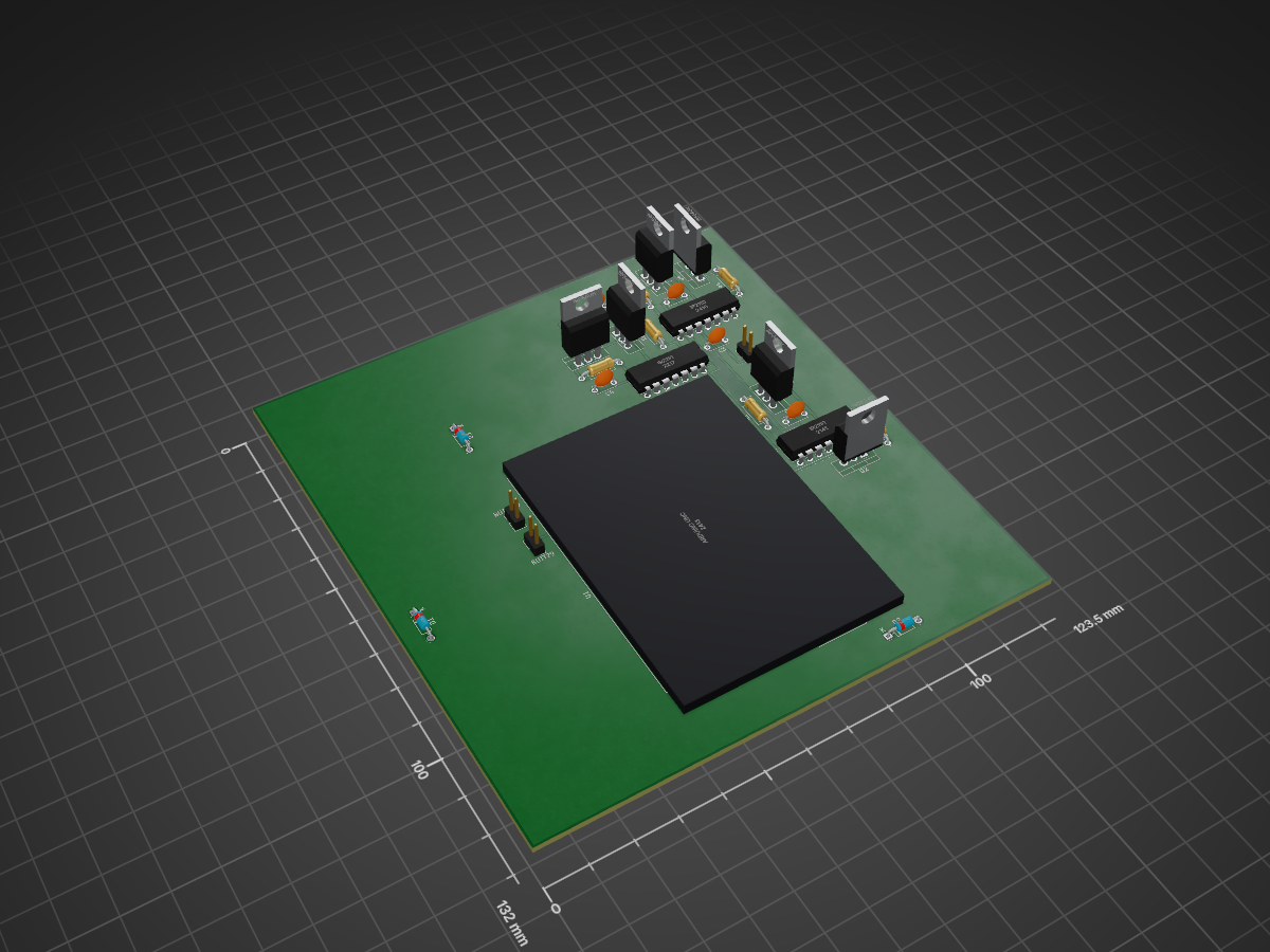
Spinning a brushless motor with no position sensor — commutating on the back-EMF zero crossings instead.
BLDC is an open-source printed circuit board by AssaadMH, from the AssaadMH/sensorless-bldc-control repository on GitHub, published under the MIT licence. It is a 2-layer board of 123.5 × 132 mm with 28 parts on 29 nets, routed with 207 tracks and 2 vias.
It is built around the IR2110L4 and IRF540N. Its parts include 6 capacitors, 6 resistors, 6 transistors, 4 ICs and 3 diodes. It belongs with the robots and motor control and sensors and measurement boards of this library.
Spinning a brushless motor with no position sensor — commutating on the back-EMF zero crossings instead.
2025·BLDC·Sensorless·Back-EMF·Arduino·Proteus·Motor control
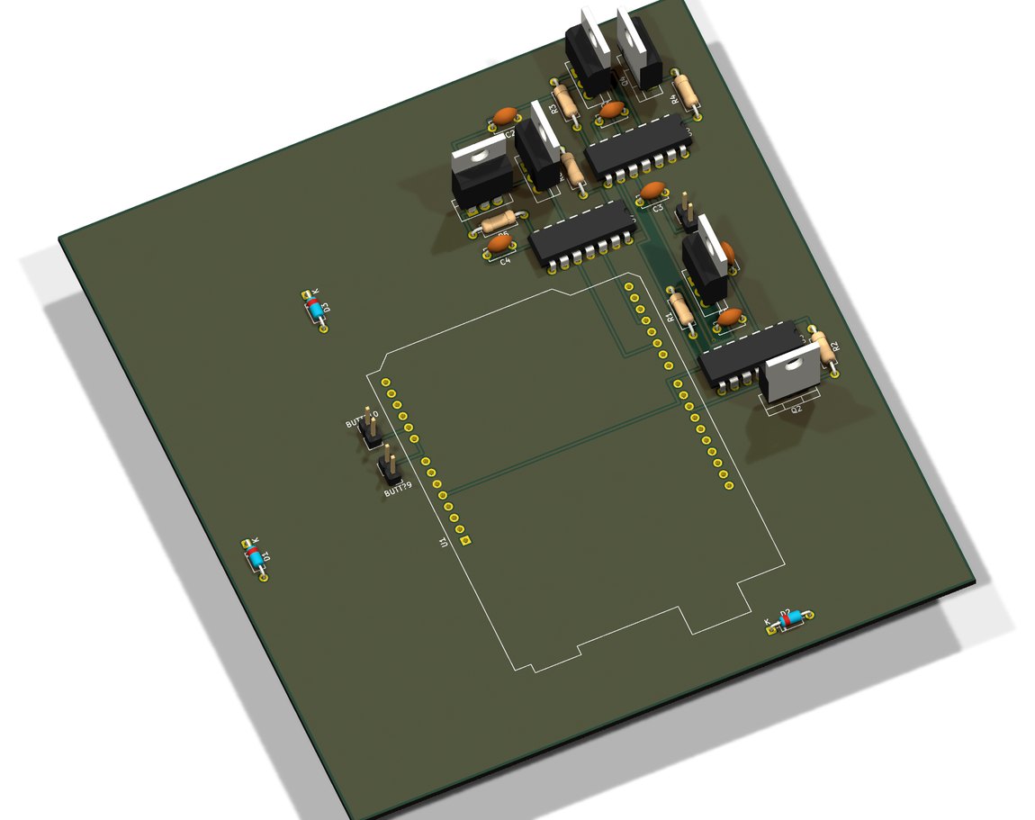
A focused study of how to run a brushless-DC motor without any Hall sensors. Removing the position sensors makes the motor cheaper and more robust, but it also removes the thing the controller normally relies on to know when to commutate — so the rotor position has to be recovered from the motor itself.
The method is back-EMF zero-crossing detection. At any instant one of the three windings is unenergised, and the voltage it generates — its back-EMF, measured against a virtual neutral point — crosses zero exactly between two commutation events. Detecting that crossing, waiting the right electrical angle, and stepping the PWM to the next phase keeps the motor in sync with no sensor at all.
The work covers the electrical and mechanical model of the motor, the commutation and PWM logic, and a Proteus simulation alongside the Arduino implementation — the standard progression of proving the idea in simulation before trusting it to real windings, which is exactly where sensorless schemes tend to bite.
captures/
docs/
kicad/Everything in this repository is my own work. It builds on the following, which are not mine and are used under their own licences:
Lassaad Mahmoudi — assaadmahmoudi0@gmail.com
https://linkedin.com/in/mahmoudi-assaad
| Qty | Value | Footprint | References |
|---|---|---|---|
| 6 | 10k | Resistor_THT:R_Axial_DIN0207_L6.3mm_D2.5mm_P10.16mm_Horizontal | R1, R2, R3, R4, R5, R6 |
| 6 | 1nF | Capacitor_THT:C_Disc_D5.0mm_W2.5mm_P5.00mm | C1, C2, C3, C4, C5, C6 |
| 6 | IRF540N | Package_TO_SOT_THT:TO-220-3_Vertical | Q1, Q2, Q3, Q4, Q5, Q6 |
| 3 | 1N4148 | Diode_THT:D_DO-35_SOD27_P7.62mm_Horizontal | D1, D2, D3 |
| 3 | IR2110 | Package_DIP:DIP-14_W7.62mm | U5, U6, U7 |
| 2 | BUTTON | Connector_PinHeader_2.54mm:PinHeader_1x02_P2.54mm_Vertical | BUTT?9, BUTT?10 |
| 1 | 12V | Connector_PinHeader_2.54mm:PinHeader_1x02_P2.54mm_Vertical | B1 |
| 1 | ARDUINO UNO | Module:Arduino_UNO_R3 | U1 |
AssaadMH/sensorless-bldc-control
Spinning a brushless motor with no position sensor — commutating on the back-EMF zero crossings instead.

chgopireddy/Full-Bridge-Class-D-Audio-Amplifier
LTspice Model for Full Bridge Class D, Voltage Mode Control, Peak Current Mode Control


ahan-halder/Audio-Power-Amplification-using-Class-D-Topology
Class D Amplifier

kj-49/path-pilot
A self-navigating robot built on an AVR128DB28 microcontroller

MadsRudolph/62768-energy-system
Team project for 62768 Electrical Energy Systems (DTU, June 2026, 3-week course). We design and build a complete electrical energy system per the course requirement spec (Kravspecifikation), from idea to a working…

technoas123/classD_amplifier
Discrete Class-D amplifier using 555, LM358, IR2110, and MOSFET half-bridge—built in KiCad with ngspice simulation.

cclienti/tig-welder
A DIY TIG welder that can be plugged to a traditionnal stick welder or to a high current source

arcoslab/open-coroco-legacy
COmpliant RObot COntroller is a free software project aiming to create an impedance controller based on a stm32 microcontroller using bldc motors and strain gauges.
It measures 123.5 × 132 mm and has 2 copper layers, 1.6 mm thick.
28 parts, built around the IR2110L4 and IRF540N. The full list of its parts is on this page, with links to each part's symbol and footprint where PCBKit's library has them.
From the AssaadMH/sensorless-bldc-control repository on GitHub, at the commit this page was made from: the board is kicad/BLDC/BLDC.kicad_pcb. PCBKit opens the board in the browser, with nothing to install.
Its repository publishes it under the MIT licence: you may reuse it on that licence's terms (keep the author's notice, and for a copyleft licence share your changes alike).