2 layers80 × 36.2 mm

 Ardenryst/pinball-led-strober3
Device to trigger mods via existing lights.
Strober board is an open-source printed circuit board by Ardenryst, from the Ardenryst/pinball-led-strober repository on GitHub, published under the MIT licence. It is a 2-layer board of 70 × 30 mm with 25 parts on 19 nets, routed with 114 tracks and 0 vias.
It is built around the ATTINY85-20PU, EL817 and BC237, with the BS170 among its other parts. Its parts include 6 diodes, 5 resistors, 4 connectors, 3 capacitors and 3 ICs. It belongs with the AVR (ATmega, ATtiny) boards of this library.


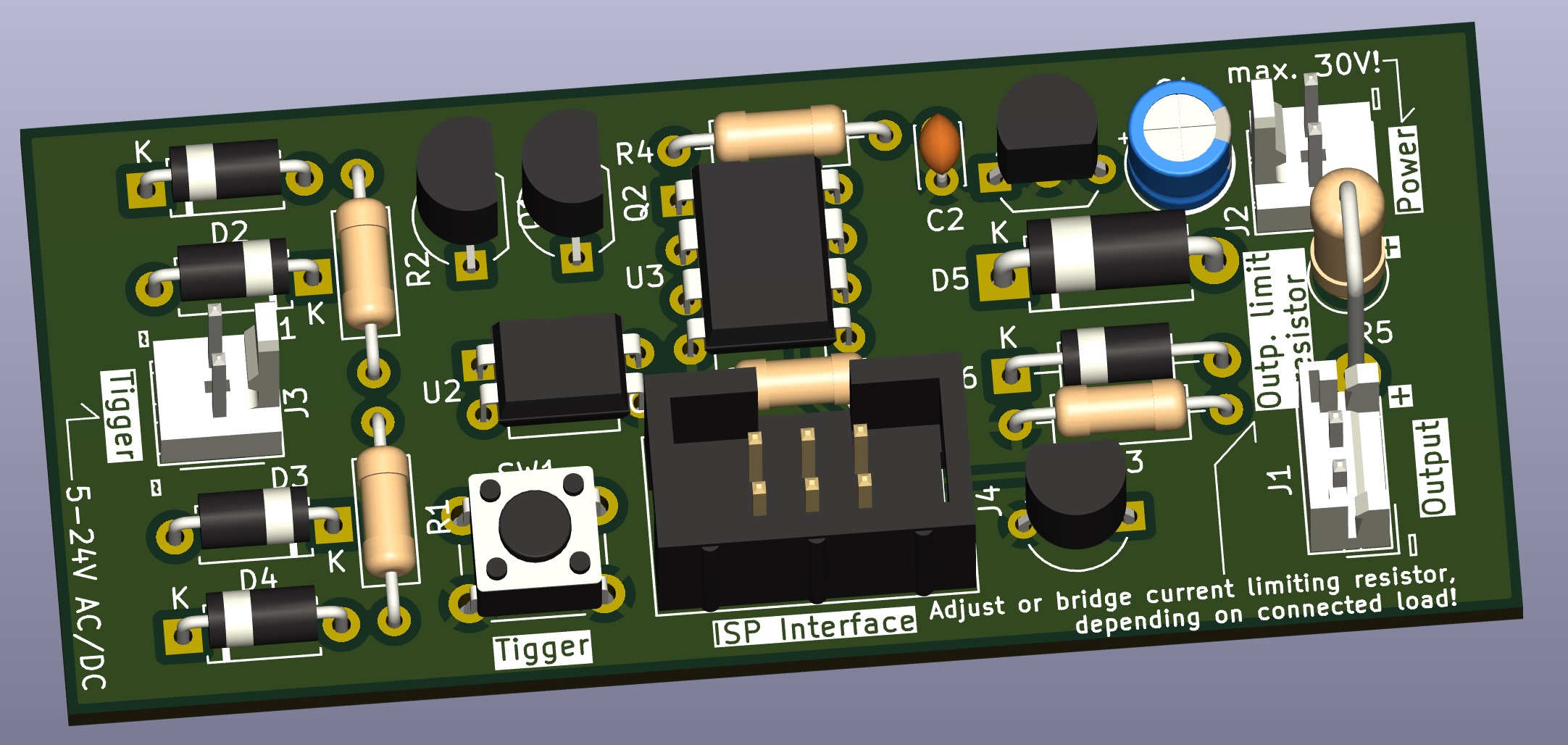
The hardware is build around the Attiny85 microcontroller (MCU), a cheap yet capable chip. To program the firmware onto the controller, an ISP (in-system programmer) is needed. You can also use something like an Arduino with the correct sketch loaded onto it.
The electronics need an external supply of 8-30V DC, reverse polarity protected local regulation is on board. The animation is triggered by an external current, the board is intended to be connected to an existing lamp and triggers as soon as this turns on. The trigger input can accept a wide voltage range of 5 to at least 24V, with no concern to polarity. For testing there is also a trigger button on the board itself that simulates an external event. Trigger input is galvanically isolated from rest of curcuit via an opto-coupler, to avoid issues with matrix switching or split power rails.
The output is connected to the board supply voltage through a current limiting resistor (R5), that has to be selected for the connected load or bridged with a jumper, if not needed. The MCU controls the output with a 12bit PWM signal, thus allowing 4096 levels of brightness with smooth fading. Output is protected against back EMF from inductive loads (e.g. EL-Wire power supply) and can supply up to 500mA of continious current.
The PCB design can either be send to a manufacturer (use the includes Gerber-files) or build on a commonly availible 10x23 hole proto board. Both options share the same physical board size of 30x70mm. Take a look into the interactive bill of materials bom-folder for what parts need to be sourced - it also greatly helps in assembly!
| Qty | Value | Footprint | References |
|---|---|---|---|
| 4 | D_45deg | Diode_THT:D_A-405_P7.62mm_Horizontal | D1, D2, D3, D4 |
| 2 | 10k | Resistor_THT:R_Axial_DIN0207_L6.3mm_D2.5mm_P10.16mm_Horizontal | R3, R4 |
| 2 | BC237 | Package_TO_SOT_THT:TO-92_Inline_Wide | Q1, Q2 |
| 2 | Conn_01x02 | Connector_Molex:Molex_KK-254_AE-6410-02A_1x02_P2.54mm_Vertical | J2, J3 |
| 1 | 100n | Capacitor_THT:C_Disc_D3.0mm_W2.0mm_P2.50mm | C2 |
| 1 | 100n | Resistor_THT:R_Axial_DIN0207_L6.3mm_D2.5mm_P10.16mm_Horizontal | C3 |
| 1 | 2k | Resistor_THT:R_Axial_DIN0207_L6.3mm_D2.5mm_P10.16mm_Horizontal | R1 |
| 1 | 4.7u | Capacitor_THT:CP_Radial_D5.0mm_P2.50mm | C1 |
| 1 | 68 | Resistor_THT:R_Axial_DIN0207_L6.3mm_D2.5mm_P10.16mm_Horizontal | R2 |
| 1 | ATtiny85-20P | Package_DIP:DIP-8_W7.62mm | U3 |
| 1 | AVR-ISP-6 | Connector_IDC:IDC-Header_2x03_P2.54mm_Vertical | J4 |
| 1 | BS170 | Package_TO_SOT_THT:TO-92_Inline_Wide | Q3 |
| 1 | Conn_01x02 | Connector_JST:JST_EH_B2B-EH-A_1x02_P2.50mm_Vertical | J1 |
| 1 | D | Diode_THT:D_A-405_P10.16mm_Horizontal | D6 |
| 1 | D | Diode_THT:D_DO-15_P10.16mm_Horizontal | D5 |
| 1 | EL817 | Package_DIP:DIP-4_W7.62mm | U2 |
| 1 | L78L05_TO92 | Package_TO_SOT_THT:TO-92_Inline_Wide | U1 |
| 1 | SW_Push | Button_Switch_THT:SW_PUSH_6mm | SW1 |
| 1 | ~ | Resistor_THT:R_Axial_DIN0411_L9.9mm_D3.6mm_P5.08mm_Vertical | R5 |


greenjacketgirl/SDR_Receiver
This project is an attempt at designing and building a Software Defined Radio receiver that has the capabilities of listening to frequencies ranging from 500kHz to 50MHz utlizing the board designed, a sound card, and…


DoESLiverpool/doorbot-setup
Scripts to install the software required to deploy the Raspberry Pi DoorBots

ibaldachini/C64NIKI2
This work is licensed under a [Creative Commons Attribution-NonCommercial-ShareAlike 4.0 International License][cc-by-nc-sa].
It measures 70 × 30 mm and has 2 copper layers, 1.6 mm thick.
25 parts, built around the ATTINY85-20PU, EL817, BC237 and BS170. The full list of its parts is on this page, with links to each part's symbol and footprint where PCBKit's library has them.
From the Ardenryst/pinball-led-strober repository on GitHub, at the commit this page was made from: the board is strober_board/strober_board.kicad_pcb and its schematic strober_board/strober_board.kicad_sch. PCBKit opens the board in the browser, with nothing to install.
Its repository publishes it under the MIT licence: you may reuse it on that licence's terms (keep the author's notice, and for a copyleft licence share your changes alike).