
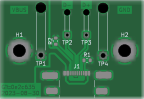
2 layers41.1 × 18.3 mm

Bamses Øhlhäfvarstoppur
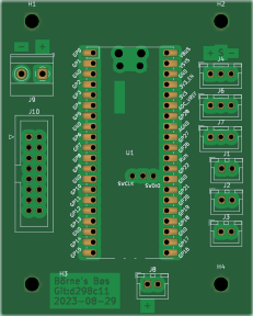
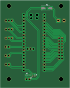
Boes is an open-source printed circuit board by AntarktisZ11, from the AntarktisZ11/boes repository on GitHub. It is a 2-layer board of 61 × 76.2 mm with 18 parts on 38 nets, routed with 91 tracks and 0 vias.
Its parts include 9 connectors, 2 resistors, 1 IC, 1 diode and 1 transistor. It belongs with the RP2040 boards of this library.
This is Bamses Øhlhäfvarstoppur also called Bøs.
TODO Desc. the rules of häfv.
TODO
TODO
Rough cost estimate: 1000-800kr
Interactive BoM (Download and view in browser.)
Interactive BoM (Download and view in browser.)
Interactive BoM (Download and view in browser.)

The following tools and libraries are required to compile and flash the Pico.
Install Pico Arduino core (if not already prepared):
# Initialize arduino-cli
arduino-cli config init

# Add Pico url to additional_urls like this:
additional_urls: [https://github.com/earlephilhower/arduino-pico/releases/download/global/package_rp2040_index.json]

# Update index to download rp2040 config
arduino-cli core update-index

# Download Pico cores
arduino-cli core install rp2040:rp204
Install the required libraries:
# Note: 'arduino-cli lib install <library>' installs <library>
# and all its dependencies.

# Adafruit library required to driver the led matrix.
arduino-cli lib install "Adafruit Protomatter"

# Protothread / simulated threads in software to schedule
# timer, display and button controllers.
arduino-cli lib install "ArduinoThread"After the prerequisites are satisfied you should be able to compile and upload the binary to the Pico.
# Compile and upload binary.
# (Note: For me <serial> was set to /dev/ttyACM0)
arduino-cli compile -u -p <serial> -b rp2040:rp2040:rpipicow display/display.ino| Qty | Value | Footprint | References |
|---|---|---|---|
| 4 | MountingHole | MountingHole:MountingHole_3.2mm_M3 | H1, H2, H3, H4 |
| 1 | +5V External | TerminalBlock_Phoenix:TerminalBlock_Phoenix_MKDS-1,5-2-5.08_1x02_P5.08mm_Horizontal | J9 |
| 1 | 10k | Resistor_SMD:R_0603_1608Metric | R1 |
| 1 | 2N7000 | Package_TO_SOT_SMD:SOT-23 | Q1 |
| 1 | Buzzer | Connector_JST:JST_XH_B2B-XH-A_1x02_P2.50mm_Vertical | J8 |
| 1 | D_Schottky | Diode_SMD:D_SMA-SMB_Universal_Handsoldering | D1 |
| 1 | HUB75 Display ctrl | Connector_IDC:IDC-Header_2x08_P2.54mm_Vertical | J10 |
| 1 | PicoW | RPi_Pico:RPi_PicoW_SMD_TH | U1 |
| 1 | Pot_J | Connector_JST:JST_XH_B3B-XH-A_1x03_P2.50mm_Vertical | J4 |
| 1 | R | Resistor_SMD:R_0603_1608Metric | R2 |
| 1 | SW_A | Connector_JST:JST_XH_B2B-XH-A_1x02_P2.50mm_Vertical | J1 |
| 1 | SW_B | Connector_JST:JST_XH_B2B-XH-A_1x02_P2.50mm_Vertical | J2 |
| 1 | SW_C | Connector_JST:JST_XH_B2B-XH-A_1x02_P2.50mm_Vertical | J3 |
| 1 | Sens_J | Connector_JST:JST_XH_B3B-XH-A_1x03_P2.50mm_Vertical | J6 |
| 1 | Sens_P | Connector_JST:JST_XH_B3B-XH-A_1x03_P2.50mm_Vertical | J7 |


VoronDesign/Voron-Hardware
Cool Hardware designed by the Voron Design group


hackclub/OnBoard
💡 Join 1,000 teenagers and make your first PCB with a $100 grant!

VoronDesign/Voron-Tap
Tap is a nozzle-based z-probe for the V2 and Trident printer designs. The entire toolhead moves to trigger an optical switch. Tap offers many advantages:

Luos-io/luos_engine
Open-source and real-time orchestrator for cyber-physical-systems, to easily design, test and deploy embedded applications and digital twins.


Twotoz/C5VRX
Ultra-minimal, zero-CPU 5.8 GHz analog FPV video receiver using ESP32-C5 Wi-Fi 6 PHY MODEM_DIAG, BitScrambler WBFM demodulation & resistor DAC CVBS
It measures 61 × 76.2 mm and has 2 copper layers, 1.6 mm thick.
18 parts. The full list of its parts is on this page, with links to each part's symbol and footprint where PCBKit's library has them.
From the AntarktisZ11/boes repository on GitHub, at the commit this page was made from: the board is pcb/boes.kicad_pcb and its schematic pcb/boes.kicad_sch. PCBKit opens the board in the browser, with nothing to install.
Its repository states no licence, so its author keeps all rights: ask AntarktisZ11 before reusing the design.