4 layers100 × 75 mm

 Angelpele/Integrated_FOC_BLDC_Actuator
Design and development of a portable, self contained closed loop Field Oriented Controller (FOC) for Brushless DC (BLDC) motors built on the ESP32 S3 via a custom designed PCB.
ESP32 Motor Controller is an open-source printed circuit board by Angelpele, from the Angelpele/Integrated_FOC_BLDC_Actuator repository on GitHub, published under the MIT licence. It is a 4-layer board of 52.8 × 56.4 mm with 154 parts on 114 nets, routed with 1,264 tracks and 270 vias.
It is built around the MCP2551-I/SN-HG, ESP32-S3-WROOM-1-N8 and DRV8302DCAR, with the MT6701CT-AKD-R, BMI270 and TLV75733PDBV among its other parts. Its parts include 54 capacitors, 43 resistors, 11 diodes, 7 transistors and 5 ICs. It belongs with the robots and motor control boards and the ESP32 boards of this library.


A portable, self-contained closed loop Field Oriented Controller (FOC) for Brushless DC (BLDC) motors built on the ESP32-S3 via a custom designed PCB. This project focuses on the development of a robust FOC controller for BLDC motors to be integrated into future robotic systems, such as robotic arms or other kind of robots. The controller combines the advantages of different motor technologies, offering:
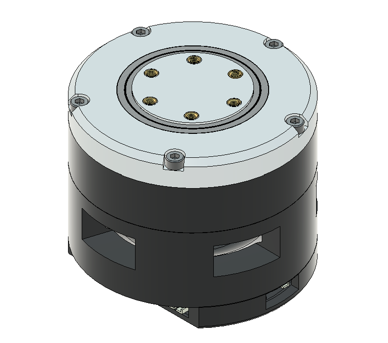
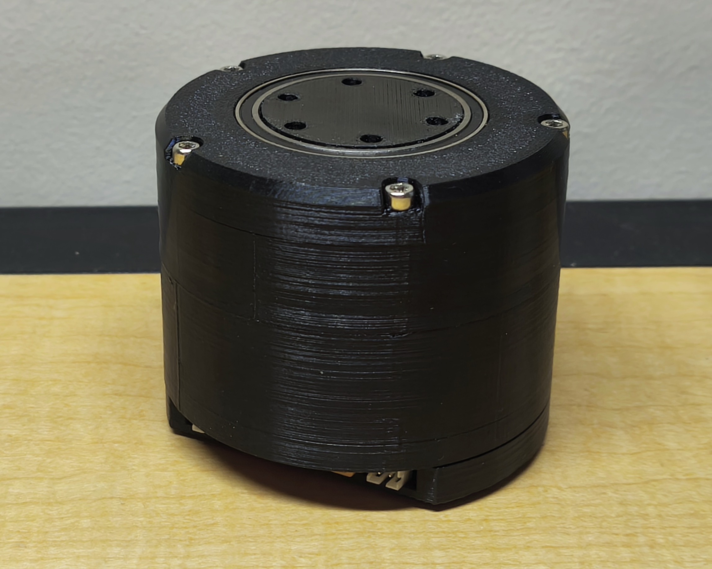
Both CAD and 3D printed preliminary models
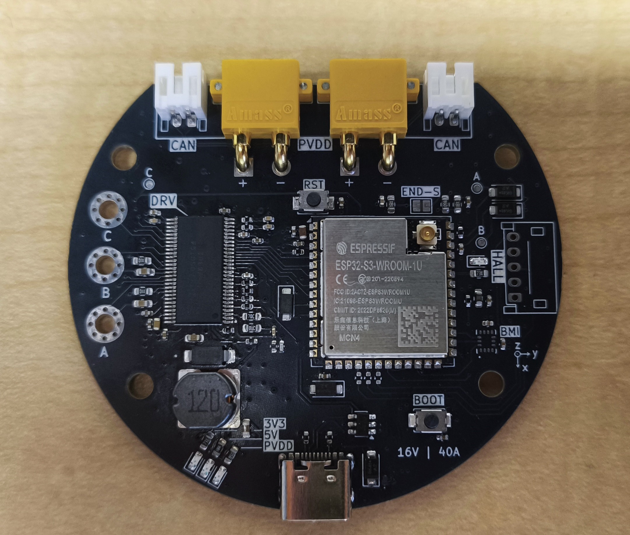
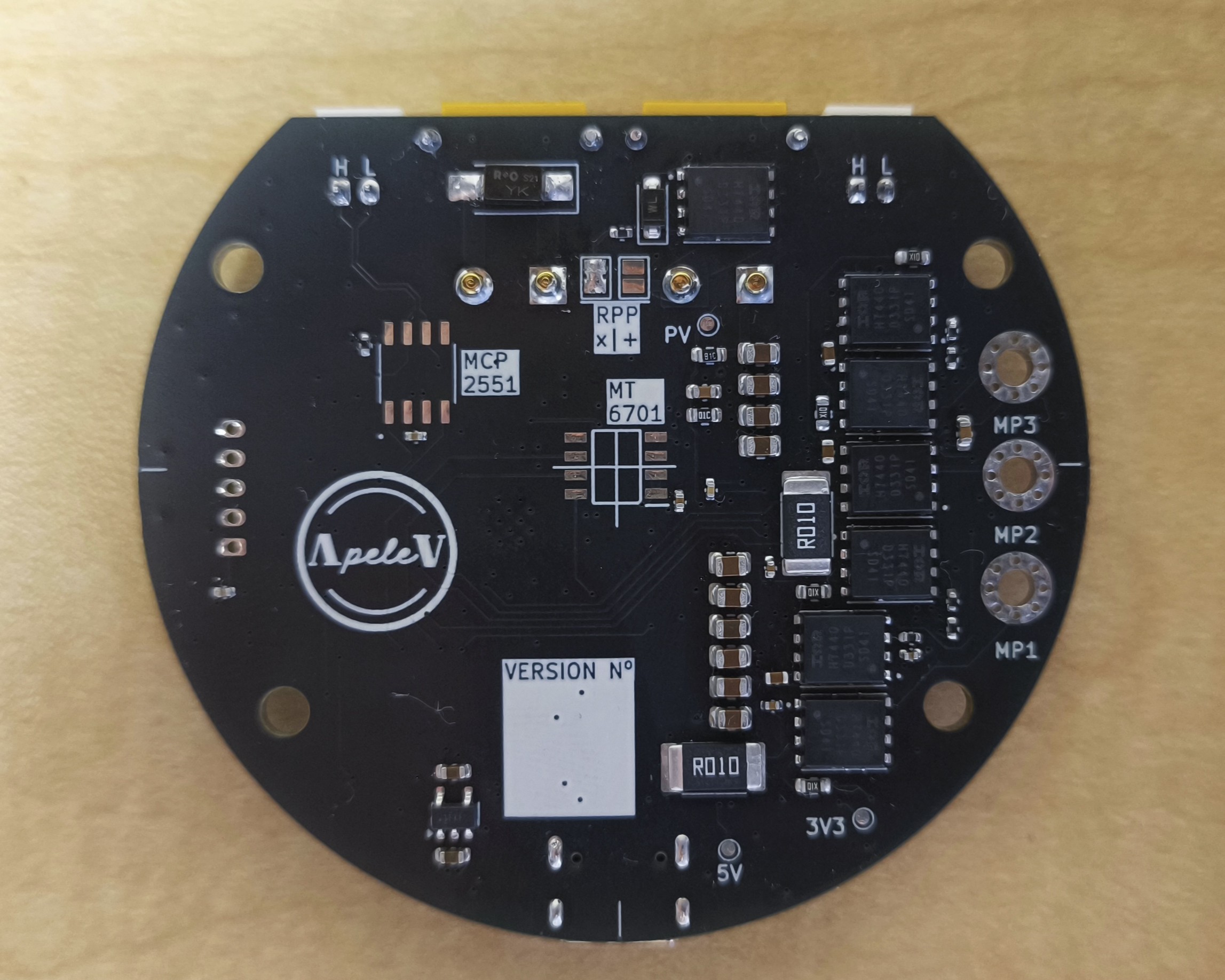
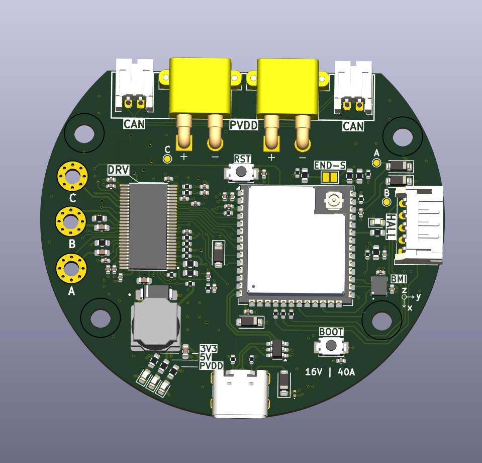
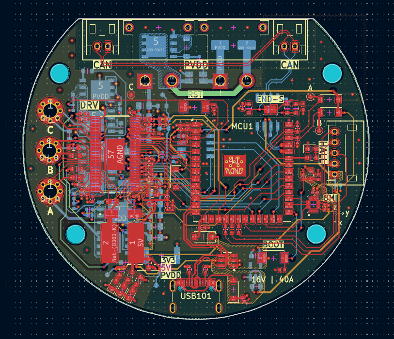
Soldered PCB V1
ESP32_Motor_Controller_V1.pdf.ESP32_Motor_Controller_V2.pdf.
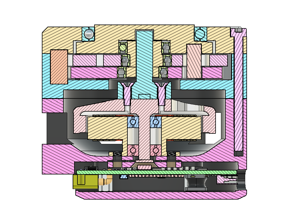
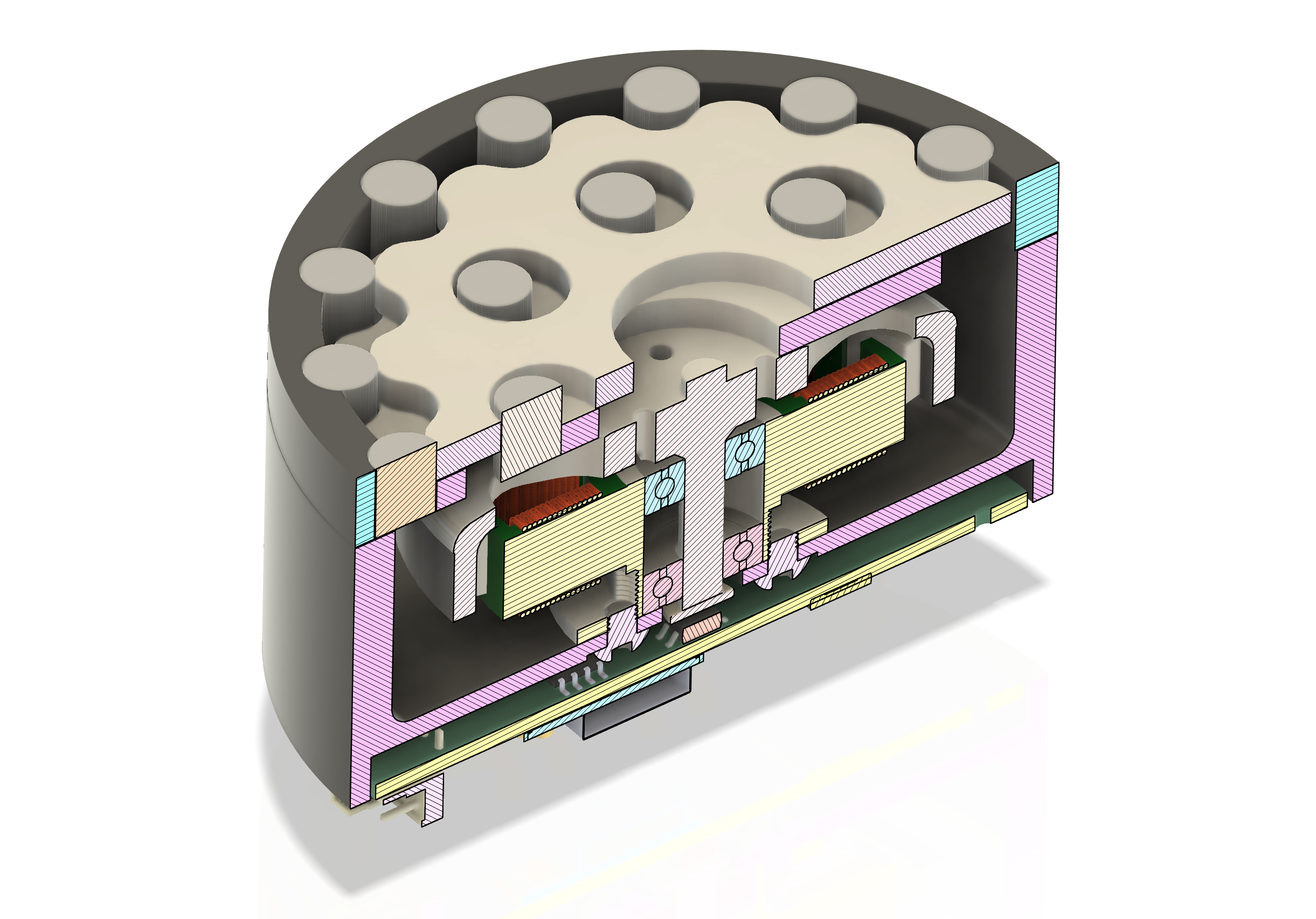
Mechanical CAD Design
The main task runs a three-state machine:
SYSTEM_INIT → SYSTEM_CALIBRATION → SYSTEM_RUNNINGA hardware timer (APB clock / 80 divider = 1 MHz, alarm at 50 µs) triggers task notifications at divided rates:
| Task | Rate | Core | Priority |
|---|---|---|---|
focLoop | 20 kHz | 1 | 10 |
magLoop | 5 kHz | 1 | 9 |
drvLoop | 500 Hz | 0 | 8 |
telemetryLoop | 100 Hz | 0 | 2 |
All shared data (drv_pkg, mag_pkg) is protected by FreeRTOS mutexes.
DRV::update_spwm() runs three stages:
elec_offset from the MT6701 reading at alignment.electrical_freq from 2 Hz to target_electrical_freq (20 Hz default) at 100 Hz/s.elec_offset + pole pairs (7) to compute instantaneous electrical angle.Motor parameters (5010 750KV, 14 poles, 270 mΩ phase resistance, 40 A max) are defined as constexpr in DRV.h.
DC_CAL pin pulse at startup, sanity-checked against 12-bit midpoint (valid range 1000–3000)I_C = -(I_A + I_B)debug_mode_enabled flag bypasses the state machine for rapid hardware-in-the-loop testing.DRV::set_override, MT6701::set_override) for bench testing without a valid magnetic field or full power stage.Integration with ROS2 and a graphical PID tuning interface are planned for future iterations.
drv8302.pdf)ESp32_S3_WROOM.pdf)| Qty | Value | Footprint | References |
|---|---|---|---|
| 13 | 0.1uF | Capacitor_SMD:C_0402_1005Metric | C202, C204, C205, C305, C322, C402, C406, C409, C501, C502, C503, C507, C508 |
| 10 | 10uF | Capacitor_SMD:C_0805_2012Metric | C104, C105, C106, C107, C108, C109, C110, C111, C112, C113 |
| 9 | 10k | Resistor_SMD:R_0402_1005Metric | R103, R201, R303, R304, R305, R403, R410, R415, R509 |
| 6 | 10R | Resistor_SMD:R_0603_1608Metric | R401, R402, R406, R407, R411, R412 |
| 6 | FH4008GS | Package_DFN_QFN:PQFN-8-EP_6x5mm_P1.27mm_Generic | Q401, Q402, Q403, Q404, Q405, Q406 |
| 5 | 1N4002 | Diode_SMD:D_SOD-123 | D102, D302, D401, D402, D403 |
| 4 | 0.1uF | Capacitor_SMD:C_0603_1608Metric | C306, C307, C308, C321 |
| 4 | 100k | Resistor_SMD:R_0402_1005Metric | R310, R404, R409, R414 |
| 4 | 1uF | Capacitor_SMD:C_0603_1608Metric | C114, C115, C201, C320 |
| 4 | MountingHole | MountingHole:MountingHole_3.2mm_M3 | MP_1, MP_2, MP_3, MP_4 |
| 3 | 0.1uF | Capacitor_SMD:C_0805_2012Metric | C312, C315, C316 |
| 3 | 0R | Resistor_SMD:R_0402_1005Metric | R501, R502, R503 |
| 3 | 1nF | Capacitor_SMD:C_0402_1005Metric | C318, C403, C404 |
| 3 | 2.2 uF | Capacitor_SMD:C_0805_2012Metric | C401, C405, C408 |
| 2 | 0.01R | Resistor_SMD:R_2512_6332Metric | R405, R408 |
| 2 | 100R | Resistor_SMD:R_0603_1608Metric | R506, R507 |
| 2 | 10k | Resistor_SMD:R_0603_1608Metric | R308, R312 |
| 2 | 2.2nF | Capacitor_SMD:C_0402_1005Metric | C309, C310 |
| 2 | 2.2uF | Capacitor_SMD:C_0805_2012Metric | C311, C313 |
| 2 | 3V3 | LED_SMD:LED_0603_1608Metric | D201, D204 |
| 2 | 5,1k | Resistor_SMD:R_0402_1005Metric | R101, R102 |
| 2 | 560pF | Resistor_SMD:R_0402_1005Metric | C504, C505 |
| 2 | 56R | Resistor_SMD:R_0603_1608Metric | R202, R205 |
| 2 | 56R | Resistor_SMD:R_0402_1005Metric | R301, R302 |
| 2 | TS-1088-AR02016 | TS-1088-AR02016:SW_TS-1088-AR02016 | SW1, SW2 |
| 2 | XT30PW-M | XT30PW-M:AMASS_XT30PW-M | J101, J102 |
| 1 | -k | Inductor_SMD:L_0603_1608Metric | FB |
| 1 | 0.015uF | Capacitor_SMD:C_0402_1005Metric | C304 |
| 1 | 0.022uF | Capacitor_SMD:C_0402_1005Metric | C303 |
| 1 | 100k | Resistor_SMD:R_0603_1608Metric | R313 |
| 1 | 1100R | Resistor_SMD:R_0603_1608Metric | R204 |
| 1 | 121R | Resistor_SMD:R_0603_1608Metric | R504 |
| 1 | 12uH | SM7850 Inductor:SM7850 | L301 |
| 1 | 12uH | Capacitor_SMD:C_0603_1608Metric | C319 |
| 1 | 150R | Resistor_SMD:R_0603_1608Metric | R203 |
| 1 | 15pF | Capacitor_SMD:C_0402_1005Metric | C317 |
| 1 | 16V | LED_SMD:LED_0603_1608Metric | D203 |
| 1 | 1uF | Capacitor_SMD:C_0402_1005Metric | C506 |
| 1 | 2.2uF | Capacitor_SMD:C_0603_1608Metric | C302 |
| 1 | 200k | Resistor_SMD:R_0402_1005Metric | R307 |
| 1 | 22uF | Capacitor_SMD:C_0805_2012Metric | C203 |
| 1 | 3.3k | Resistor_SMD:R_0402_1005Metric | R311 |
| 1 | 3V3 | TestPoint:TestPoint_Pad_D1.0mm | TP9 |
| 1 | 4.7uF | Capacitor_SMD:C_0805_2012Metric | C314 |
| 1 | 4k7 | Resistor_SMD:R_0402_1005Metric | R505 |
| 1 | 52.3k | Resistor_SMD:R_0603_1608Metric | R309 |
| 1 | 5V | LED_SMD:LED_0603_1608Metric | D202 |
| 1 | 5V | TestPoint:TestPoint_Pad_D1.0mm | TP13 |
| 1 | 86.6k | Resistor_SMD:R_0402_1005Metric | R306 |
| 1 | AVDD | TestPoint:TestPoint_Pad_D1.0mm | AV |
| 1 | A_SENSE | TestPoint:TestPoint_Pad_D1.0mm | A |
| 1 | B360 | B3030A:B3030A | D301 |
| 1 | BMI270 | BMI270:XDCR_BMI270 | U501 |
| 1 | BZT52C18 | Diode_SMD:D_SOD-123 | D101 |
| 1 | B_SENSE | TestPoint:TestPoint_Pad_D1.0mm | B |
| 1 | CAN | Jumper:SolderJumper-2_P1.3mm_Open_Pad1.0x1.5mm | JP3 |
| 1 | CAN1 | Connector_JST:JST_PH_S2B-PH-K_1x02_P2.00mm_Horizontal | J502 |
| 1 | CAN2 | Connector_JST:JST_PH_S2B-PH-K_1x02_P2.00mm_Horizontal | J503 |
| 1 | C_SENSE | TestPoint:TestPoint_Pad_D1.0mm | C |
| 1 | Conn_01x01_Pin | Connector_PinHeader_2.00mm:PinHeader_1x01_P2.00mm_Vertical | Ext_Cap101 |
| 1 | DRV8302DCAR | DRV8302:DRV8302 | U301 |
| 1 | ESP32-S3-WROOM-1 | RF_Module:ESP32-S3-WROOM-1U | ESP 32 |
| 1 | GND | TestPoint:TestPoint_Pad_D1.0mm | GND |
| 1 | Hall Encoder | Connector_JST:JST_PH_S5B-PH-K_1x05_P2.00mm_Horizontal | J501 |
| 1 | MCP2551-I_SN | MCP2551-I_SN:SOIC127P599X175-8N | U502 |
| 1 | MT6701CT-AKD | MT6701CT-STD-R:SOIC127P600X175-8N | IC501 |
| 1 | NTC 10k | Resistor_SMD:R_0603_1608Metric | TH1 |
| 1 | PESDNC2 | Diode_SMD:D_0201_0603Metric | TVS101 |
| 1 | PVDD | TestPoint:TestPoint_Pad_D1.0mm | PV |
| 1 | Pad401 | MountingHole:MountingHole_2.5mm_Pad_Via | MP1 |
| 1 | Pad402 | MountingHole:MountingHole_2.5mm_Pad_Via | MP2 |
| 1 | Pad403 | MountingHole:MountingHole_2.5mm_Pad_Via | MP3 |
| 1 | SMAJ30CA | Diode_SMD:D_SMC | TVS103 |
| 1 | SOLDER - RPP | Jumper:SolderJumper-2_P1.3mm_Open_Pad1.0x1.5mm | JP1 |
| 1 | SOLDER - XRPP | Jumper:SolderJumper-2_P1.3mm_Open_Pad1.0x1.5mm | JP2 |
| 1 | SRV05-4 | Package_TO_SOT_SMD:SOT-23-6 | TVS102 |
| 1 | TLV75733PDBV | Package_TO_SOT_SMD:SOT-23-5 | U2 |
| 1 | USB_C 3.1 | Connector_USB:USB_C_Receptacle_Palconn_UTC16-G | USB-C |
| 1 | XRS80P06F | XRS80P06F:XRS80P06F | Q1 |


jakepoz/jpbms
JPBms is a simple BMS for solar charging and balancing a 3-cell lithium ion battery.


Squantor/DiySolderingStation
Do it yourself soldering station

Motokichirou/gamma-spectrometer
NaI(Tl) gamma spectrometer: STM32G474 + R1307 PMT + 4-board stack, KiCad schematics, LTspice simulations


Foosa7/koi_8x8
The controller board for Koi 8×8. Carries a Raspberry Pi Pico (RP2040) and hosts up to 8 daughterboards in PCIe-x4 card-edge slots, addressing each board's DAC/ADC over a shared SPI bus. Formerly codenamed MOBO.
It measures 52.8 × 56.4 mm and has 4 copper layers, 1.66 mm thick.
154 parts, built around the MCP2551-I/SN-HG, ESP32-S3-WROOM-1-N8, DRV8302DCAR and MT6701CT-AKD-R. The full list of its parts is on this page, with links to each part's symbol and footprint where PCBKit's library has them.
From the Angelpele/Integrated_FOC_BLDC_Actuator repository on GitHub, at the commit this page was made from: the board is Hardware/ESP32_Motor_Controller/ESP32_Motor_Controller.kicad_pcb and its schematic Hardware/ESP32_Motor_Controller/CONTROLLER [2].kicad_sch. PCBKit opens the board in the browser, with nothing to install.
Its repository publishes it under the MIT licence: you may reuse it on that licence's terms (keep the author's notice, and for a copyleft licence share your changes alike).