
2 layers143.5 × 70 mm

Taiko JVS for Namco System 256
IO256 is an open-source printed circuit board by AnalogDragon, from the AnalogDragon/Taiko-256 repository on GitHub. It is a 2-layer board of 170 × 120 mm with 270 parts on 231 nets, routed with 1,928 tracks and 651 vias.
It is built around the STM32G030C8T6, SP3485EEN and TL084CN, with the SRV05-4, XC6206P332MR and 1N4148WS among its other parts. Its parts include 119 resistors, 58 capacitors, 38 diodes, 26 connectors and 8 ICs. It belongs with the STM32 boards of this library.


Taiko JVS for Namco System 256 (246)
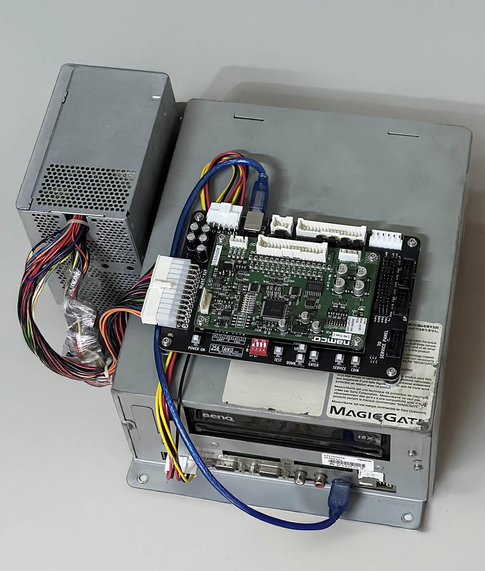
Previously, running Taiko on Namco System 256 required many accessories, such as a JVS (MINI-JV PCB), a SIF PCB, and an intermediate FUTA PCB, making the setup overly complex.
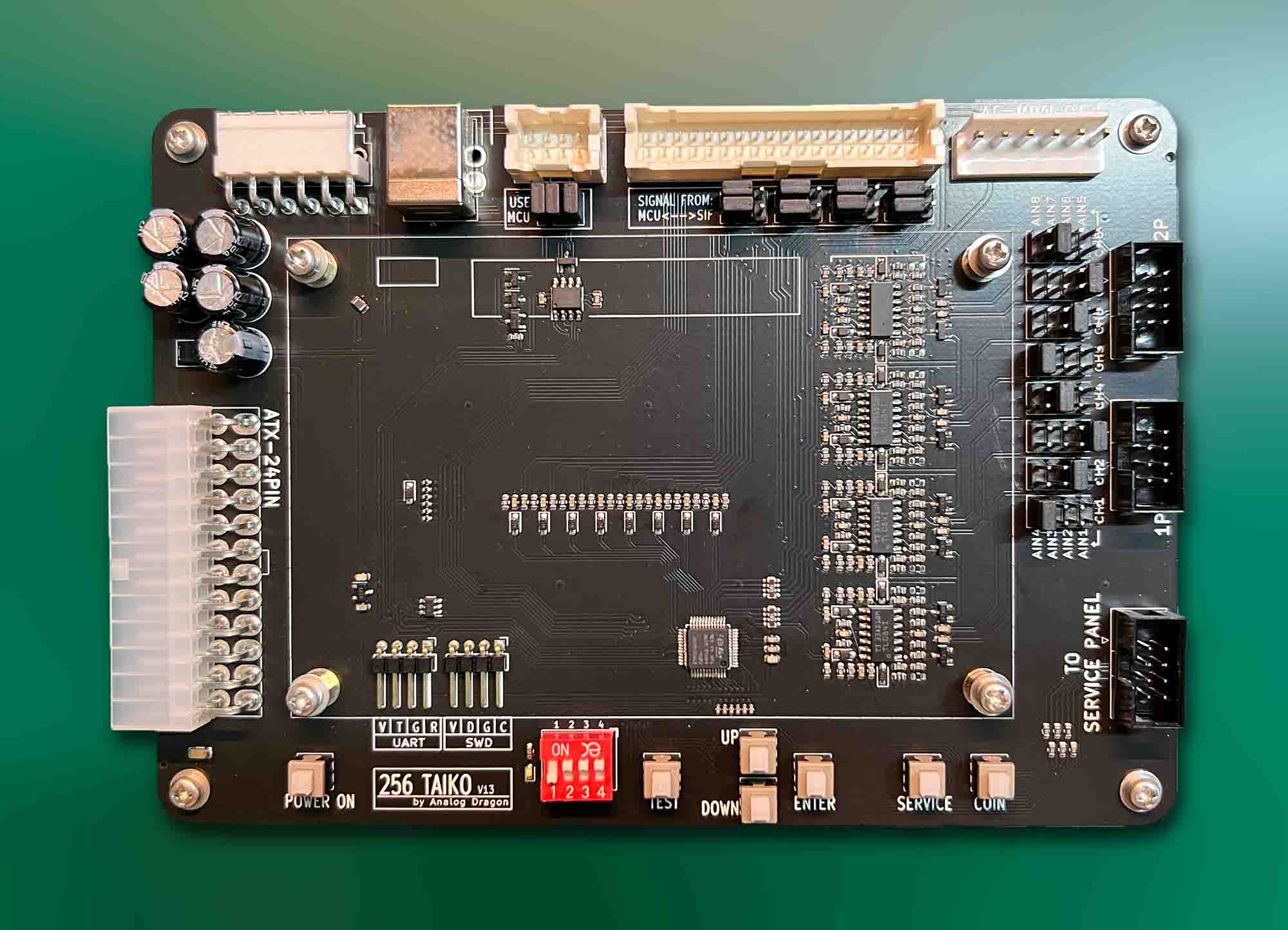
This project's PCB can fully replace the three boards mentioned above. It features two independent Taiko interfaces, an onboard Service button, and supports direct power supply via ATX.
Alternatively, this PCB can also be used to replace only the SIF PCB and FUTA PCB while still using the original MINI-JV PCB. However, this does not provide a better experience.
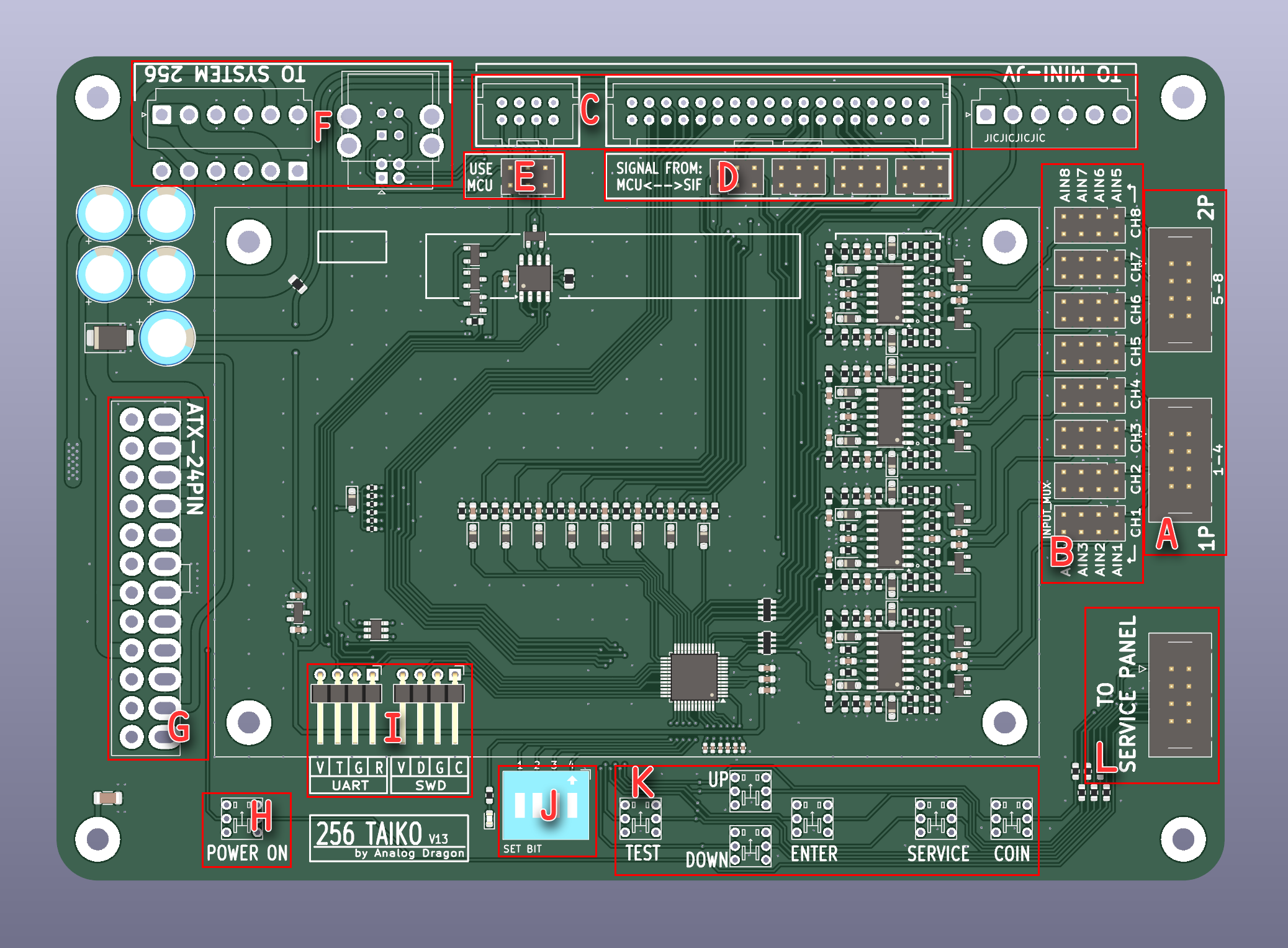
Labels in the image:
| Qty | Value | Footprint | References |
|---|---|---|---|
| 24 | 1K | Resistor_SMD:R_0603_1608Metric | R2, R15, R16, R17, R18, R23, R24, R25, R26, R27, R28, R29, R104, R105, R106, R107 +8 |
| 24 | 1N4148WS | Diode_SMD:D_SOD-323_HandSoldering | D1, D2, D3, D14, D16, D17, D18, D19, D20, D21, D22, D27, D28, D29, D30, D31 +8 |
| 16 | 200K | Resistor_SMD:R_0603_1608Metric | R36, R38, R40, R42, R44, R46, R48, R50, R76, R78, R80, R82, R84, R86, R88, R90 |
| 10 | 100nF/50V | Capacitor_SMD:C_0603_1608Metric | C36, C37, C38, C40, C42, C43, C44, C45, C46, C47 |
| 10 | 4.7K | Resistor_SMD:R_0603_1608Metric | R12, R35, R56, R57, R58, R59, R96, R97, R98, R99 |
| 10 | BAT54S/BAV99 | Package_TO_SOT_SMD:SOT-23 | D10, D11, D12, D13, D23, D24, D25, D26, D35, D36 |
| 8 | 0R | Resistor_SMD:R_0603_1608Metric | R45, R47, R49, R51, R85, R87, R89, R91 |
| 8 | 10K | Resistor_SMD:R_0603_1608Metric | R60, R61, R62, R63, R100, R101, R102, R103 |
| 8 | 10nF/50V | Capacitor_SMD:C_0603_1608Metric | C27, C28, C29, C30, C31, C32, C33, C34 |
| 8 | 1M | Resistor_SMD:R_0603_1608Metric | R1, R6, R13, R14, R68, R69, R70, R71 |
| 8 | 2.2nF/50V | Capacitor_SMD:C_0603_1608Metric | C1, C3, C4, C5, C16, C21, C22, C23 |
| 8 | 2.2uF/16V | Capacitor_SMD:C_0603_1608Metric | C6, C7, C8, C9, C17, C18, C19, C20 |
| 8 | 220 | Resistor_SMD:R_0603_1608Metric | R7, R8, R9, R10, R19, R20, R21, R22 |
| 8 | 3.3K | Resistor_SMD:R_0603_1608Metric | R31, R32, R33, R34, R72, R73, R74, R75 |
| 8 | 4.7uF/16V | Capacitor_SMD:C_0603_1608Metric | C10, C11, C12, C15, C24, C25, C26, C35 |
| 8 | 47R | Resistor_SMD:R_0603_1608Metric | R52, R53, R54, R55, R92, R93, R94, R95 |
| 8 | Conn_02x04_Counter_Clockwise | Connector_PinHeader_2.54mm:PinHeader_2x04_P2.54mm_Vertical | J9, J10, J11, J12, J13, J14, J15, J16 |
| 8 | NC | Resistor_SMD:R_0603_1608Metric | R37, R39, R41, R43, R77, R79, R81, R83 |
| 7 | SW_Push_DPDT | NewLib:switch_6x6 | SW1, SW2, SW3, SW4, SW5, SW6, SW8 |
| 6 | 100R | Resistor_SMD:R_0603_1608Metric | R108, R109, R110, R111, R112, R113 |
| 6 | 100nF/50V | Capacitor_SMD:C_0402_1005Metric | C41, C52, C54, C55, C57, C58 |
| 6 | 4.7K | Resistor_SMD:R_0402_1005Metric | R114, R115, R116, R117, R118, R119 |
| 5 | 470uF/25V | Capacitor_THT:CP_Radial_D8.0mm_P3.50mm | C14, C48, C49, C50, C51 |
| 5 | MINI-JV | MountingHole:MountingHole_3.2mm_M3_DIN965_Pad | H1, H2, H3, H4, H5 |
| 4 | Conn_02x03_Odd_Even | Connector_PinHeader_2.54mm:PinHeader_2x03_P2.54mm_Vertical | J18, J19, J20, J23 |
| 4 | Jumper_2_Open | NewLib:JP_0603 | JP1, JP2, JP3, JP4 |
| 4 | TL084C | Package_SO:SO-14_3.9x8.65mm_P1.27mm | U3, U4, U5, U7 |
| 3 | Conn_02x04_Counter_Clockwise | Connector_IDC:IDC-Header_2x04_P2.54mm_Vertical | J5, J7, J8 |
| 2 | 10K | Resistor_SMD:R_Array_Convex_4x0603 | RN1, RN2 |
| 2 | 10uF/16V | Capacitor_SMD:C_0603_1608Metric | C2, C39 |
| 2 | Conn_01x04 | Connector_PinHeader_2.54mm:PinHeader_1x04_P2.54mm_Horizontal | J17, J21 |
| 2 | Conn_01x06 | Connector_JST:JST_VH_B6P-VH_1x06_P3.96mm_Vertical | J3, J103 |
| 1 | 102/2KV | Capacitor_SMD:C_1206_3216Metric | C53 |
| 1 | 120R | Resistor_SMD:R_0805_2012Metric | R11 |
| 1 | 120R/100M | Resistor_SMD:R_0805_2012Metric | FB1 |
| 1 | 1N5819WS | Diode_SMD:D_SOD-323_HandSoldering | D38 |
| 1 | 1uF/25V | Capacitor_SMD:C_0603_1608Metric | C56 |
| 1 | 22uF/6.3V | Capacitor_SMD:C_0603_1608Metric | C13 |
| 1 | AO3400A | Package_TO_SOT_SMD:SOT-23 | Q2 |
| 1 | ATX-24 | NewLib:5557-2x12 | J6 |
| 1 | Conn_01x06 | Connector_JST:JST_VH_B6PS-VH_1x06_P3.96mm_Horizontal | J24 |
| 1 | Conn_02x02_Odd_Even | Connector_PinHeader_2.54mm:PinHeader_2x03_P2.54mm_Vertical | J22 |
| 1 | Conn_02x04_Odd_Even | NewLib:B08B-XADSS-N-A | J1 |
| 1 | Conn_02x18_Odd_Even | NewLib:B36B-XADSS-N-A | J4 |
| 1 | SKYBLUE_LED | LED_SMD:LED_0603_1608Metric | D15 |
| 1 | SM712_SOT23 | Package_TO_SOT_SMD:SOT-23 | D5 |
| 1 | SMBJ5.0A | Diode_SMD:D_SMB | D37 |
| 1 | SP3485 | Package_SO:SOIC-8_3.9x4.9mm_P1.27mm | U2 |
| 1 | SRV05-4 | Package_TO_SOT_SMD:SOT-23-6 | U8 |
| 1 | STM32G030C8T6 | Package_QFP:LQFP-48_7x7mm_P0.5mm | U6 |
| 1 | SW_DIP_x04 | Button_Switch_THT:SW_DIP_SPSTx04_Slide_9.78x12.34mm_W7.62mm_P2.54mm | SW7 |
| 1 | USB_B | Connector_USB:USB_B_OST_USB-B1HSxx_Horizontal | J25 |
| 1 | USB_B | Connector_USB:USB_B_TE_5787834_Vertical | J102 |
| 1 | XC6206P332MR | Package_TO_SOT_SMD:SOT-23 | U1 |


rjsc/BECom
BECom - Battery Emulator Companion - Open Source Hardware, designed to run dalathegreat/Battery-Emulator

tomrodinger/servomotor
Open-source NEMA-17 integrated servomotor (motor + closed-loop driver + controller + encoder). RS-485, Python/Arduino libraries, MCP server for AI control. Hardware, firmware and software.

butchja/esphome-jk-bms-can-PCB
HW platform for https://github.com/Ackmaniac/esphome-jk-bms-can


EdgeCoil/wiegand-bridge
ESP32-S3 Wiegand reader bridge for Home Assistant: 4-layer board, BOM and ESPHome firmware.
It measures 170 × 120 mm and has 2 copper layers, 1.6 mm thick.
270 parts, built around the STM32G030C8T6, SP3485EEN, TL084CN and SRV05-4. The full list of its parts is on this page, with links to each part's symbol and footprint where PCBKit's library has them.
From the AnalogDragon/Taiko-256 repository on GitHub, at the commit this page was made from: the board is HW/IO256/IO256.kicad_pcb and its schematic HW/IO256/IO256.kicad_sch. PCBKit opens the board in the browser, with nothing to install.
Its repository states no licence, so its author keeps all rights: ask AnalogDragon before reusing the design.