4 layers

 Alvin-Alford/PowerBox1
Add Later
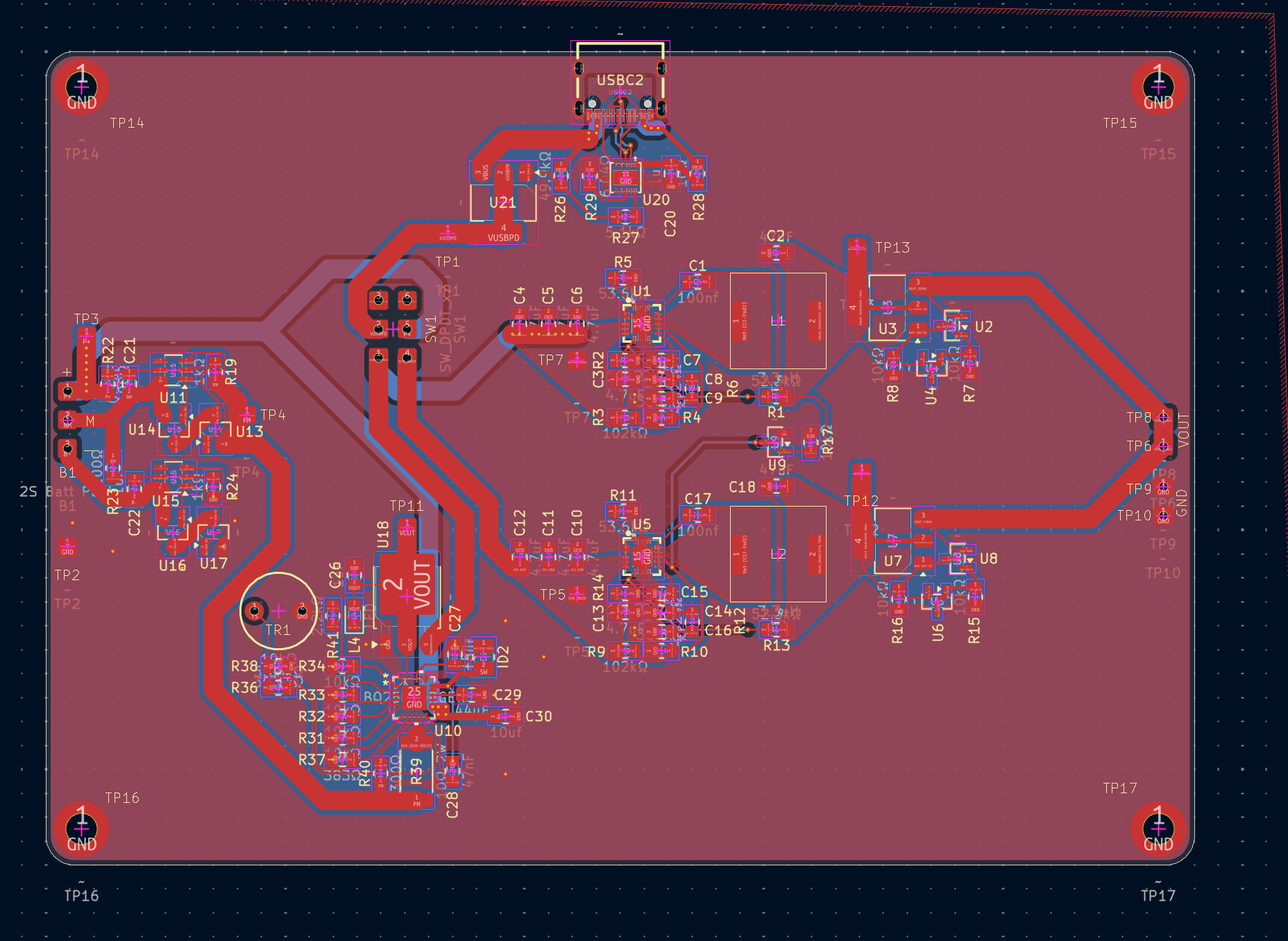
PowerBox PCB is an open-source printed circuit board by Alvin-Alford, from the Alvin-Alford/PowerBox repository on GitHub. It is a 2-layer board of 100 × 75 mm with 113 parts on 78 nets, routed with 507 tracks and 168 vias.
It is built around the MMBT3906LT1G, AO3400A and BC817, with the DW01A, TPS54620RGY and CH221K among its other parts. Its parts include 38 resistors, 26 capacitors, 21 ICs, 6 inductors and 1 switch.


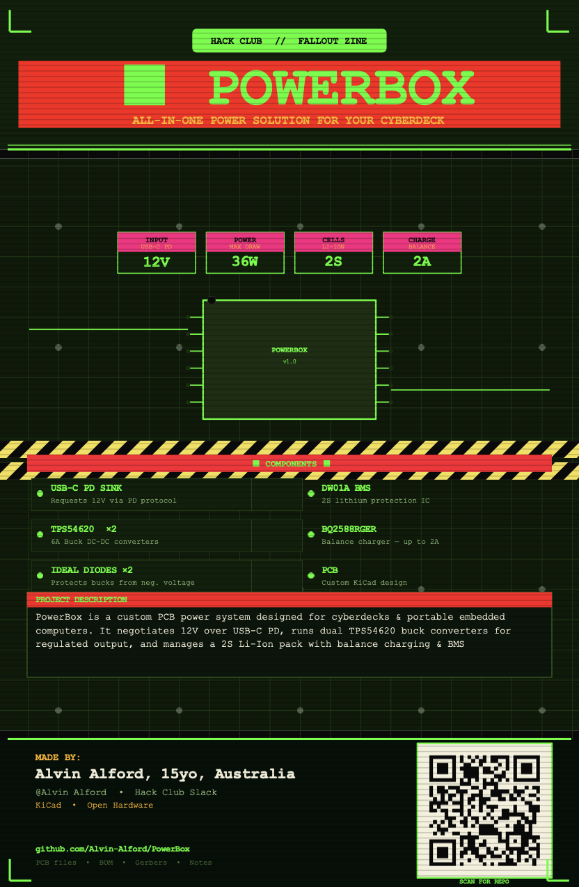
An all-in-one power solution for cyberdecks and portable embedded systems.
PowerBox is my custom-designed PCB that handles USB-C Power Delivery input, dual-cell lithium battery management, balance charging, and regulated power output, all in a single compact board. Designed to push up to 36W of power to whatever you throw at it.
PowerBox was built to power DIY cyberdecks and portable computing projects that need more juice than a standard battery banks can provide.
PowerBox is built around 7 core subsystems:
A USB-C port paired with a PD sink controller that negotiates 12V from a PD-capable charger. At full load the circuit can draw up to 36W which is well beyond what standard 5V USB can supply.
Two TPS54620 synchronous step-down converters provide regulated output voltages. The TPS54620 is a 6A, 17V capable device giving plenty of headroom for demanding loads.
When USB-C power is present, the battery-fed bucks are switched off to prevent backfeeding the charger. This creates a condition where the buck converter inputs can see negative voltages which is outside their rated range. The ideal diode circuits clamp this safely, acting as electronic diodes with near-zero forward voltage drop.
A battery management system built around the DW01A which is a popular and proven lithium-ion protection IC. Handles over-charge, over-discharge, and short-circuit protection for the cell pack.
A proper 2-series balance charger using TI's BQ2588RGER, capable of up to 2A charge current. Keeps both cells at equal state-of-charge for longevity and safety.
The PCB design files are in the PowerBox_PCB/ directory. Output gerbers and fabrication files are in Output/.
USB-C PD (12V, 36W)
        │
        ├──► Buck 1 (TPS54620) ──► Ideal Diode ──► Output Rail A
        │
        ├──► Buck 2 (TPS54620) ──► Ideal Diode ──► Output Rail B
        │
        └──► BQ2588RGER Balance Charger ──► 2S Li-Ion Pack
                                                  │
                                              DW01A BMS
                                                  │
                                            Battery Output
Why did I choose 36W / USB-C PD?
A 2S lithium pack needs to charge while simultaneously powering the system. At full system load, 15W standard USB-C isn't enough, it can't even charge an open MacBook. Requesting 12V via PD and pulling up to 3A gives the 36W headroom needed to charge the battery and run the load at the same time.
Why two cells?
More cells = more capacity. More capacity = the circuit can sustain high loads without the cells entering stress territory. A single-cell design at 36W draw would be asking for trouble (and possibly a fire).
PowerBox/
├── Notes/           # Design notes and calculations
├── Output/          # Gerber files and fabrication outputs
├── Parts/           # Bill of materials and component info
└── PowerBox_PCB/ # KiCad / PCB design files| Component | Part Number | Function |
|---|---|---|
| Buck Converter | TPS54620 | 6A, 17V synchronous step-down |
| Balance Charger | BQ2588RGER | 2S Li-Ion balance charger, 2A |
| BMS Controller | DW01A | Li-Ion protection IC |
| PD Sink | (see Parts/) | USB-C PD 12V negotiation |
See LICENSE for details.
Built by Alvin-Alford
| Qty | Value | Footprint | References |
|---|---|---|---|
| 12 | 10kΩ | Resistor_SMD:R_0805_2012Metric_Pad1.20x1.40mm_HandSolder | R2, R7, R8, R14, R15, R16, R17, R29, R31, R32, R33, R34 |
| 11 | ~ | Custom_Footprints:PAD-2x2 | TP1, TP2, TP3, TP4, TP5, TP7, TP9, TP10, TP11, TP12, TP13 |
| 9 | 4.7uF | Capacitor_SMD:C_0805_2012Metric_Pad1.18x1.45mm_HandSolder | C3, C4, C5, C6, C10, C11, C12, C13, C18 |
| 5 | MMBT3906LT1G | Package_TO_SOT_SMD:SOT-23 | U2, U4, U6, U8, U12 |
| 4 | 1kΩ | Resistor_SMD:R_0805_2012Metric_Pad1.20x1.40mm_HandSolder | R19, R21, R24, R25 |
| 4 | AO3400A | Package_TO_SOT_SMD:SOT-23_Handsoldering | U13, U14, U16, U17 |
| 4 | LED | LED_SMD:LED_0805_2012Metric_Pad1.15x1.40mm_HandSolder | L3, L4, L5, L6 |
| 4 | ~ | Custom_Footprints:M3-Pad | TP14, TP15, TP16, TP17 |
| 3 | 2.2kΩ | Resistor_SMD:R_0805_2012Metric_Pad1.20x1.40mm_HandSolder | R26, R27, R41 |
| 3 | 47uF | Capacitor_SMD:C_1210_3225Metric_Pad1.33x2.70mm_HandSolder | C2, C19, C23 |
| 3 | DMP6023LE-13 | Package_TO_SOT_SMD:SOT-223 | U3, U7, U21 |
| 2 | 0.1uF | Capacitor_SMD:C_0805_2012Metric_Pad1.18x1.45mm_HandSolder | C21, C22 |
| 2 | 100kΩ | Resistor_SMD:R_0805_2012Metric_Pad1.20x1.40mm_HandSolder | R28, R30 |
| 2 | 100nf | Capacitor_SMD:C_0805_2012Metric_Pad1.18x1.45mm_HandSolder | C1, C17 |
| 2 | 100Ω | Resistor_SMD:R_0805_2012Metric_Pad1.20x1.40mm_HandSolder | R22, R23 |
| 2 | 102kΩ | Resistor_SMD:R_0805_2012Metric_Pad1.20x1.40mm_HandSolder | R3, R9 |
| 2 | 10uf | Capacitor_SMD:C_0805_2012Metric_Pad1.18x1.45mm_HandSolder | C27, C30 |
| 2 | 18uF | Capacitor_SMD:C_0805_2012Metric_Pad1.18x1.45mm_HandSolder | C9, C16 |
| 2 | 2.2uF | Capacitor_SMD:C_0805_2012Metric_Pad1.18x1.45mm_HandSolder | C7, C15 |
| 2 | 3.3uH | Buck_TPS54620:IND-SMD_L8.5-W8.0_PSPMAA0803H-330M-ANP | L1, L2 |
| 2 | 30pF | Capacitor_SMD:C_0805_2012Metric_Pad1.18x1.45mm_HandSolder | C8, C14 |
| 2 | 36.5kΩ | Resistor_SMD:R_0805_2012Metric_Pad1.20x1.40mm_HandSolder | R4, R10 |
| 2 | 4.02kΩ | Resistor_SMD:R_0805_2012Metric_Pad1.20x1.40mm_HandSolder | R6, R12 |
| 2 | 52.3kΩ | Resistor_SMD:R_0805_2012Metric_Pad1.20x1.40mm_HandSolder | R1, R13 |
| 2 | 53.6kΩ | Resistor_SMD:R_0805_2012Metric_Pad1.20x1.40mm_HandSolder | R5, R11 |
| 2 | BC817 | Package_TO_SOT_SMD:SOT-23 | U19, U22 |
| 2 | DW01A | Package_TO_SOT_SMD:SOT-23-6_Handsoldering | U11, U15 |
| 2 | TPS54620 | Buck_TPS54620:VQFN-14_L3.5-W3.5-P0.50-TL-EP_TPS54622RHLT | U1, U5 |
| 2 | ~ | Custom_Footprints:PAD-2x2-ThroughHole | TP18, TP19 |
| 1 | 10kΩ | Custom_Footprints:ThermistorPads | TR1 |
| 1 | 10Ω_2W | Resistor_SMD:R_2512_6332Metric_Pad1.40x3.35mm_HandSolder | R39 |
| 1 | 1uF | Capacitor_SMD:C_0805_2012Metric_Pad1.18x1.45mm_HandSolder | C20 |
| 1 | 1uh | Inductor_SMD:L_1008_2520Metric_Pad1.43x2.20mm_HandSolder | ID2 |
| 1 | 2N7002 | Package_TO_SOT_SMD:SOT-23 | U9 |
| 1 | 2S Batt Pack | Custom_Footprints:2S Batt Pack | B1 |
| 1 | 30.1kΩ | Capacitor_SMD:C_0805_2012Metric_Pad1.18x1.45mm_HandSolder | R38 |
| 1 | 300Ω | Resistor_SMD:R_0805_2012Metric_Pad1.20x1.40mm_HandSolder | R40 |
| 1 | 383Ω | Capacitor_SMD:C_0805_2012Metric_Pad1.18x1.45mm_HandSolder | R37 |
| 1 | 47nF | Capacitor_SMD:C_0805_2012Metric_Pad1.18x1.45mm_HandSolder | C28 |
| 1 | 5.23kΩ | Capacitor_SMD:C_0805_2012Metric_Pad1.18x1.45mm_HandSolder | R36 |
| 1 | BQ25887RGER | BQ25887RGER:VQFN24_RGE_TEX | U10 |
| 1 | CH221K | Package_TO_SOT_SMD:SOT-23-6 | U23 |
| 1 | SW_DPDT_x2 | Custom_Footprints:SwitchPads | SW1 |
| 1 | USBC_Port | Custom_Footprints:USB-C_SMD-TYPE-C-31-M-12_1 | USBC2 |

gabeak2/KASM_PCB
Thesis Project - PCB to drive actuators for the Adaptive Secondary Mirror at Keck


HeyPCB/quack-core
Brain board for the Open Duck Mini: Pi Zero 2W carrier, 14-servo STS bus, fused 2S power path in stitched copper zones (15-18 A battery side), USB-C charging with balancing, IMU.

epremeaux/AVTokyo_2022_Badge
AVTokyo 2022 event badge PCB, firmware and server code.

malikkelly8/ECE445-FADEX
Notebook for Malik Kelly to keep track of progress in ECE 445. Also a way for the rest of the FadeX staff to see progress.

whowechina/densha_pico
Special thanks to community projects and developers. And also these projects: RPSiliconKiCad: https://github.com/HeadBoffin/RPSiliconKiCad

It measures 100 × 75 mm and has 2 copper layers, 1.6 mm thick.
113 parts, built around the MMBT3906LT1G, AO3400A, BC817 and DW01A. The full list of its parts is on this page, with links to each part's symbol and footprint where PCBKit's library has them.
From the Alvin-Alford/PowerBox repository on GitHub, at the commit this page was made from: the board is PowerBox_PCB/PowerBox_PCB.kicad_pcb and its schematic PowerBox_PCB/BMS.kicad_sch. PCBKit opens the board in the browser, with nothing to install.
Its repository states no licence, so its author keeps all rights: ask Alvin-Alford before reusing the design.