2 layers100 × 20 mm

 Altairu/AltairMD_V91
AltairMD_V9
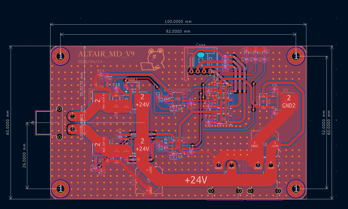
AltairMD V9 is an open-source printed circuit board by Altairu, from the Altairu/AltairMD_V9 repository on GitHub. It is a 2-layer board of 100 × 60 mm with 54 parts on 28 nets, routed with 300 tracks and 393 vias.
It is built around the IR2302STRPBF, TLP152 and L7812, with the AOD4184A among its other parts. Its parts include 14 resistors, 11 capacitors, 10 diodes, 6 ICs and 4 transistors.


AltairMD_V9 は、小型かつ高出力なモーター制御を目的とした、MOSFET方式のHブリッジモータードライバーです。
V7の回路に非常に近いです. https://github.com/Altairu/AltairMD_V7
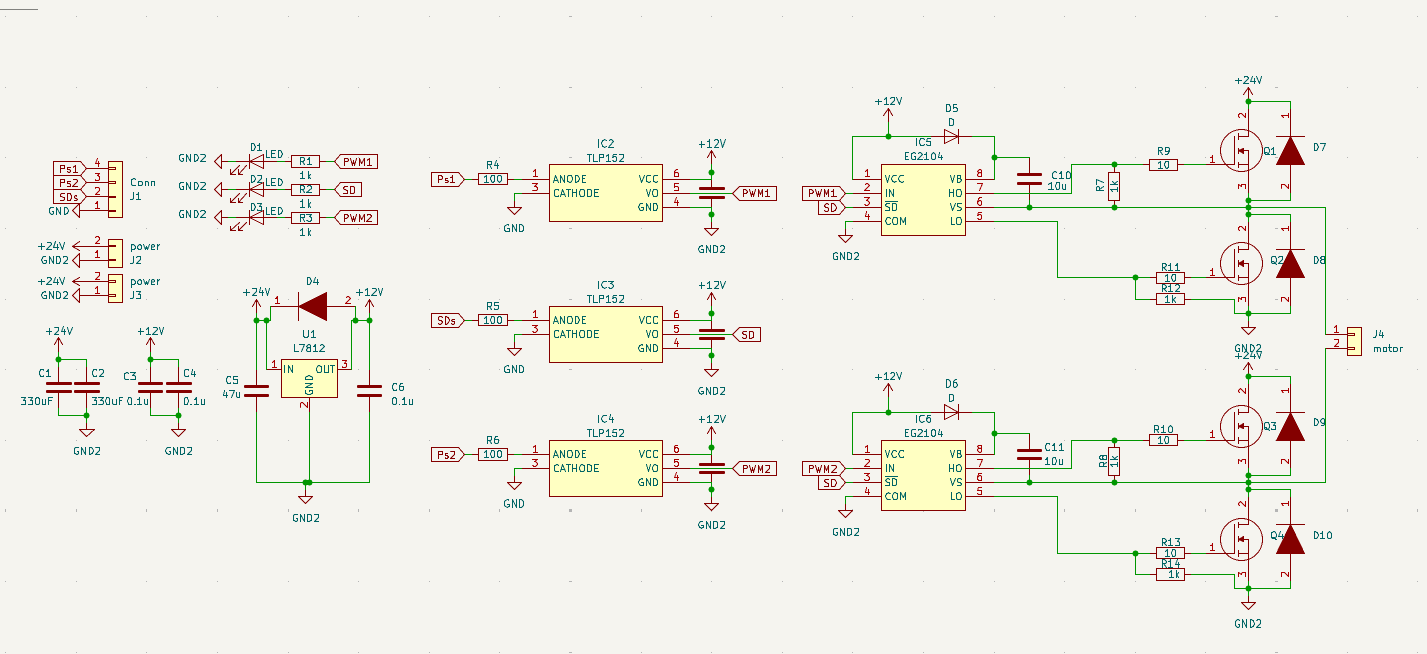
AOD4184Aを採用することで、低オン抵抗(標準 $7.0\text{m}\Omega$)を実現。小型ながら大きな電流を扱える設計になっています。
EG2104ゲートドライバを搭載することで、ブートストラップ方式によるハイサイドMOSFETの確実な駆動を可能にしています。これにより、24V系でもスイッチング損失を抑えた効率的な動作が可能です。
大電流パスには太い配線と十分なビアを配置し、D-PAKパッケージの底面から基板への放熱を最適化しています。
回路図
PCB
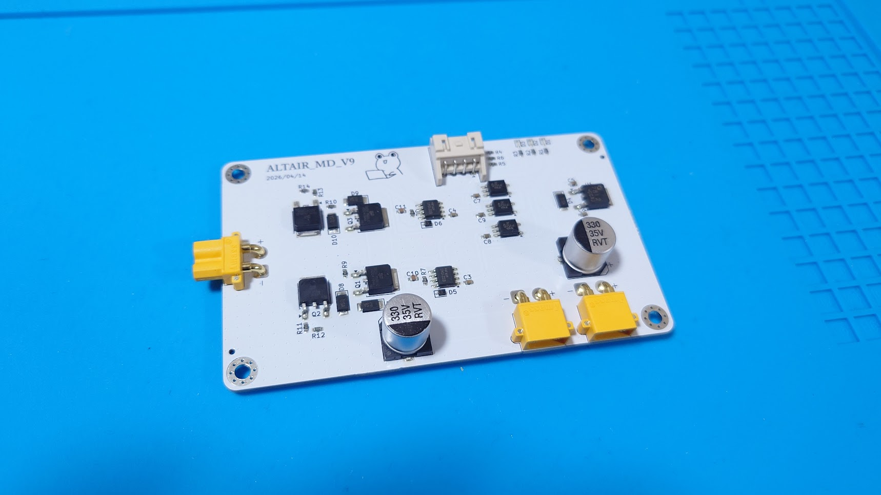
実装後
| Qty | Value | Footprint | References |
|---|---|---|---|
| 7 | 1k | Resistor_SMD:R_0603_1608Metric | R1, R2, R3, R7, R8, R12, R14 |
| 6 | 0.1u | Capacitor_SMD:C_0603_1608Metric | C3, C4, C6, C7, C8, C9 |
| 5 | CMS11 | Diode_SMD:D_SOD-128 | D4, D7, D8, D9, D10 |
| 4 | 10 | Resistor_SMD:R_0603_1608Metric | R9, R10, R11, R13 |
| 4 | AOD4184A | Package_TO_SOT_SMD:TO-252-2 | Q1, Q2, Q3, Q4 |
| 4 | MountingHole | MountingHole:MountingHole_3.2mm_M3_Pad_Via | H1, H2, H3, H4 |
| 3 | 100 | Resistor_SMD:R_0603_1608Metric | R4, R5, R6 |
| 3 | LED | LED_SMD:LED_0603_1608Metric | D1, D2, D3 |
| 3 | TLP152 | Package_SO:SO-5-6_4.55x3.7mm_P1.27mm | IC2, IC3, IC4 |
| 2 | 10u | Capacitor_SMD:C_0603_1608Metric | C10, C11 |
| 2 | 330uF | Capacitor_SMD:CP_Elec_10x10 | C1, C2 |
| 2 | D | Diode_SMD:D_SOD-323 | D5, D6 |
| 2 | IR2302STRPBF | Package_SO:SOIC-8_3.9x4.9mm_P1.27mm | IC5, IC6 |
| 2 | power | Connector_AMASS:AMASS_XT30PW-M_1x02_P2.50mm_Horizontal | J2, J3 |
| 1 | 47u | Capacitor_SMD:C_0603_1608Metric | C5 |
| 1 | Conn | Connector_JST:JST_XA_S04B-XASK-1_1x04_P2.50mm_Horizontal | J1 |
| 1 | L7812 | Package_TO_SOT_SMD:TO-252-2 | U1 |
| 1 | LOGO | LOGO | G*** |
| 1 | motor | Connector_AMASS:AMASS_XT30PW-F_1x02_P2.50mm_Horizontal | J4 |

Altairu/Altair_Remote_Emergency_Stop_V1
Altair_Remote_Emergency_Stop_V1

MUBARIS-KT/DC-DC_CONVERTER
This project provides the complete design and code for a DC to DC converter that steps up 12V DC to 300V DC. The project is a comprehensive solution in power electronics, including PCB design, STM32 code for PWM…


It measures 100 × 60 mm and has 2 copper layers, 1.6 mm thick.
54 parts, built around the IR2302STRPBF, TLP152, L7812 and AOD4184A. The full list of its parts is on this page, with links to each part's symbol and footprint where PCBKit's library has them.
From the Altairu/AltairMD_V9 repository on GitHub, at the commit this page was made from: the board is AltairMD_V9.kicad_pcb and its schematic AltairMD_V9.kicad_sch. PCBKit opens the board in the browser, with nothing to install.
Its repository states no licence, so its author keeps all rights: ask Altairu before reusing the design.