4 layers138.1 × 104.6 mm
V7-kaleido
vroland/epdiy-hardware
Hardware design files for EPDiy: https://github.com/vroland/epdiy.
140 parts75CC-BY-SA-4.0
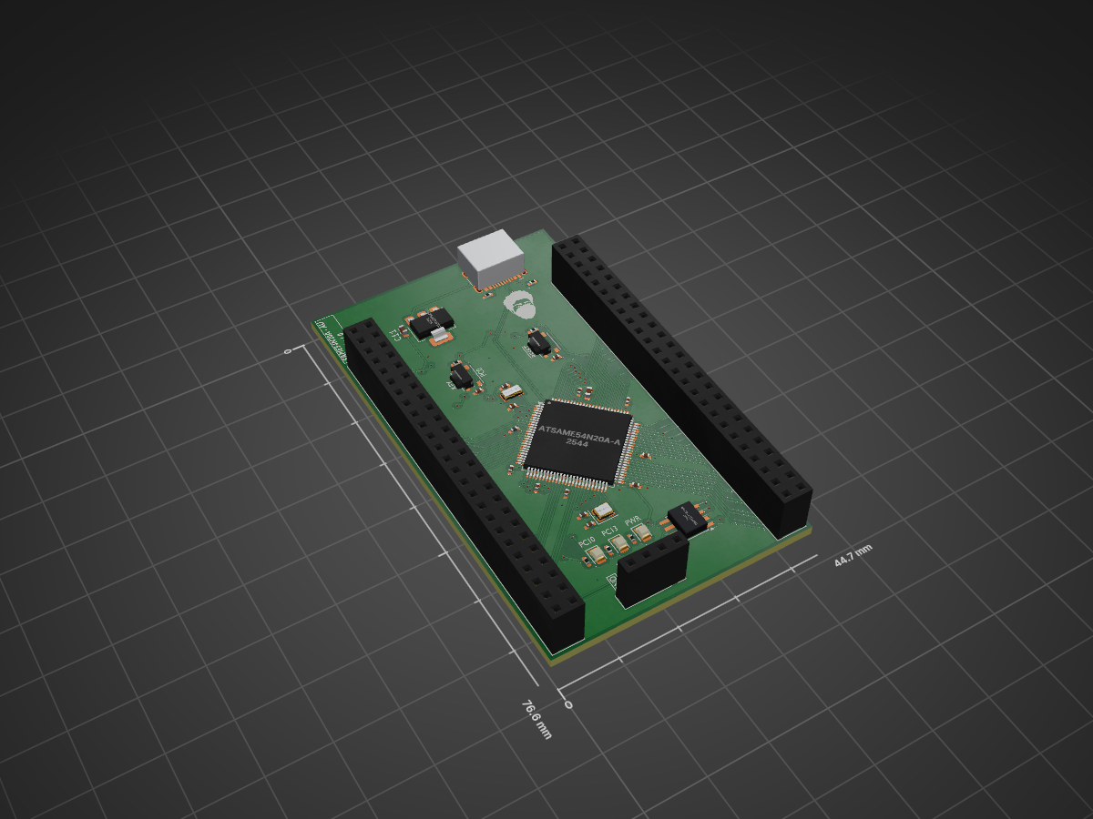
 Albinjm72/Microchip-ATSAME54-Development-Board
A fully custom development board built around the Microchip ATSAME54N20A-AU (ARM Cortex-M4F, 120MHz), designed end-to-end in KiCad — schematic, routing, and silkscreen.
ATSAME54N20A AU is an open-source printed circuit board by Albinjm72, from the Albinjm72/Microchip-ATSAME54-Development-Board repository on GitHub, published under the CERN-OHL-S-2.0 licence. It is a 2-layer board of 44.7 × 76.6 mm with 45 parts on 97 nets, routed with 1,044 tracks and 87 vias.
It is built around the ATSAME54N20A-AU, THD2528-11SD-GF and TPS7A0533PDBZ. Its parts include 15 capacitors, 12 resistors, 4 ICs, 4 connectors and 3 diodes. It belongs with the SAM D and SAM boards of this library.


A custom-designed development board built around the Microchip ATSAME54N20A-AU (ARM Cortex-M4F)
Designed end-to-end in KiCad — schematic, routing, and silkscreen.
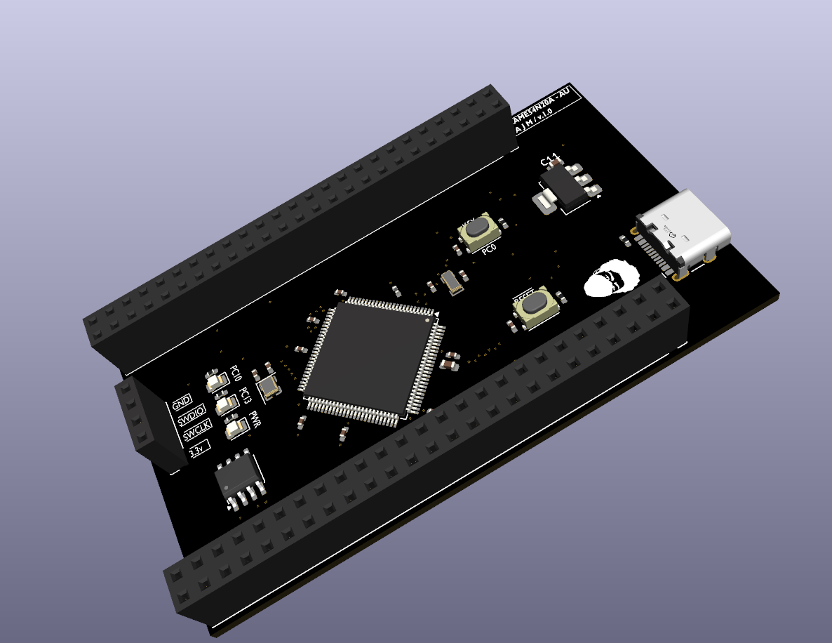
This is a fully custom development board designed from a bare microcontroller datasheet up — power architecture, signal routing, and silkscreen branding all done by hand in KiCad, not adapted from a reference design.
| Feature | Detail |
|---|---|
| MCU | Microchip ATSAME54N20A-AU — ARM Cortex-M4F, 120MHz, 1MB flash, 100-pin TQFP |
| USB | USB Type-C connector (power + native USB) |
| CAN | Onboard CAN controller/transceiver for real bus communication |
| Storage | microSD card slot (SDHC) + external QSPI flash |
| Debug | SWD programming/debug header |
| Indicators | 1x power LED, 2x user-controllable LEDs |
| I/O | Dual 2-row GPIO headers (one on each side) — breadboard-compatible pitch |
ATSAME54N20A-AU.kicad_pro in KiCad 10 or latergerber_to_order/ if you just want to order the board as-isProgram and debug via the onboard SWD header using any ARM-compatible probe (ST-Link, J-Link, Atmel-ICE, or similar), through OpenOCD/GDB or MPLAB X.
Full BOM with reference designators, values, and footprints is in production/bom.csv.
See CHANGELOG.md for what changed between board revisions.
Licensed under CERN-OHL-S v2.
🔧 Active development — first hardware revision fabricated, pending assembly and bring-up testing.
| Qty | Value | Footprint | References |
|---|---|---|---|
| 9 | 100nF | Capacitor_SMD:C_0402_1005Metric_Pad0.74x0.62mm_HandSolder | C1, C2, C3, C4, C5, C6, C7, C8, C9 |
| 9 | 10k | Resistor_SMD:R_0402_1005Metric_Pad0.72x0.64mm_HandSolder | R1, R2, R5, R6, R8, R9, R10, R11, R12 |
| 3 | 330 | Resistor_SMD:R_0402_1005Metric_Pad0.72x0.64mm_HandSolder | R3, R4, R7 |
| 2 | 12pF | Capacitor_SMD:C_0402_1005Metric_Pad0.74x0.62mm_HandSolder | C12, C13 |
| 2 | 15pF | Capacitor_SMD:C_0402_1005Metric_Pad0.74x0.62mm_HandSolder | C14, C15 |
| 2 | Conn_01x50_MountingPin | Connector_PinSocket_2.54mm:PinSocket_2x25_P2.54mm_Vertical | J6, J8 |
| 2 | SW_Push | Button_Switch_SMD:SW_Push_1P1T_NO_Vertical_Wuerth_434133025816 | SW1, SW2 |
| 1 | 0805 GREEN | LED_SMD:LED_0805_2012Metric | D1 |
| 1 | 0805 ORANGE | LED_SMD:LED_0805_2012Metric | D3 |
| 1 | 0805 RED | LED_SMD:LED_0805_2012Metric | D2 |
| 1 | 10uF | Capacitor_SMD:C_0603_1608Metric | C11 |
| 1 | 1uF | Capacitor_SMD:C_0603_1608Metric | C10 |
| 1 | 32.768kHz | Crystal:Crystal_SMD_3215-2Pin_3.2x1.5mm | Y2 |
| 1 | 600ohm@100MHz | Inductor_SMD:L_0402_1005Metric_Pad0.77x0.64mm_HandSolder | FB1 |
| 1 | ATSAME54N20A-AU | Package_QFP:TQFP-100_14x14mm_P0.5mm | U1 |
| 1 | Conn_01x04_Pin | Connector_PinSocket_2.54mm:PinSocket_1x04_P2.54mm_Vertical | J7 |
| 1 | Crystal | Crystal:Crystal_SMD_2520-4Pin_2.5x2.0mm | Y1 |
| 1 | LOGO | LOGO | G*** |
| 1 | MCP2542FDxMF | Package_SO:SOIC-8-1EP_3.9x4.9mm_P1.27mm_EP2.41x3.3mm | U4 |
| 1 | SST26VF064Bxx-xxxx-MF | SST26VF064B_SOIJ:SOIJ-8_L5.3-W5.3-P1.27-LS7.9-BL | U3 |
| 1 | THD2528-11SD-GF | easyeda2kicad:TF-SMD_THD2528-11SD-GF | Card1 |
| 1 | TPS7A0533PDBZ | Package_TO_SOT_SMD:SOT-223-3_TabPin2 | U2 |
| 1 | USB_C_Receptacle_USB2.0_16P | Connector_USB:USB_C_Receptacle_HCTL_HC-TYPE-C-16P-01A | J3 |
vroland/epdiy-hardware
Hardware design files for EPDiy: https://github.com/vroland/epdiy.


Aryan-git-byte/Soil-metrics
Portable AI-powered soil monitoring device with LTE connectivity, GPS, touchscreen interface, and real-time soil health analytics.

jackbrad1ey/water_jet_tvc
A water-propelled thrust vector control (TVC) testbed vehicle aiming to decrease the cost and time factors associated with developing TVC control algorithms

AidenBTTU/Gesture-Capture-Watch
A wristband-mounted gesture recognition system built around an STM32F411, IMU, and OLED display, with USB-C battery charging and ESD-protected I/O.


It measures 44.7 × 76.6 mm and has 2 copper layers, 1.6 mm thick.
45 parts, built around the ATSAME54N20A-AU, THD2528-11SD-GF and TPS7A0533PDBZ. The full list of its parts is on this page, with links to each part's symbol and footprint where PCBKit's library has them.
From the Albinjm72/Microchip-ATSAME54-Development-Board repository on GitHub, at the commit this page was made from: the board is ATSAME54N20A-AU.kicad_pcb and its schematic ATSAME54N20A-AU.kicad_sch. PCBKit opens the board in the browser, with nothing to install.
Its repository publishes it under the CERN-OHL-S-2.0 licence: you may reuse it on that licence's terms (keep the author's notice, and for a copyleft licence share your changes alike).