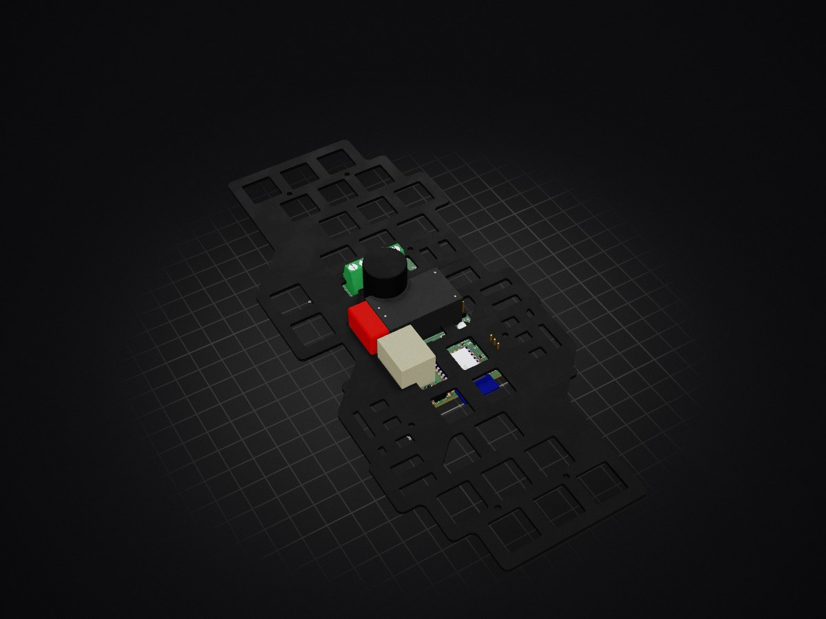
2 layers87 × 68 mm
 AlanCarvalhoEE/hap1
Home Automation Platform with custom hardware and firmware (ESP8266), a Raspberry Pi–based server, and an Android client. Features modular IoT devices, TCP/IP and MQTT messaging, and a scalable system architecture.
On off module x1 is an open-source printed circuit board by AlanCarvalhoEE, from the AlanCarvalhoEE/hap repository on GitHub. It is a 2-layer board of 46 × 77 mm with 40 parts on 43 nets, routed with 199 tracks and 124 vias.
It is built around the ESP-12E, HLK-PM12 and AMS1117-3.3, with the H11AA1, 2N7002H and S1A among its other parts. Its parts include 12 resistors, 7 capacitors, 4 ICs, 3 connectors and 2 diodes. It belongs with the home automation and IoT boards and the ESP8266 boards of this library.


A modular, self-hosted home automation platform focused on reliability, local control, and secure remote access.
The system is designed around a Raspberry Pi server that centralizes application logic and device state, ESP8266-based IoT modules for field control, and a mobile application as the primary user interface. Communication between components is event-driven and optimized for embedded and low-latency environments.
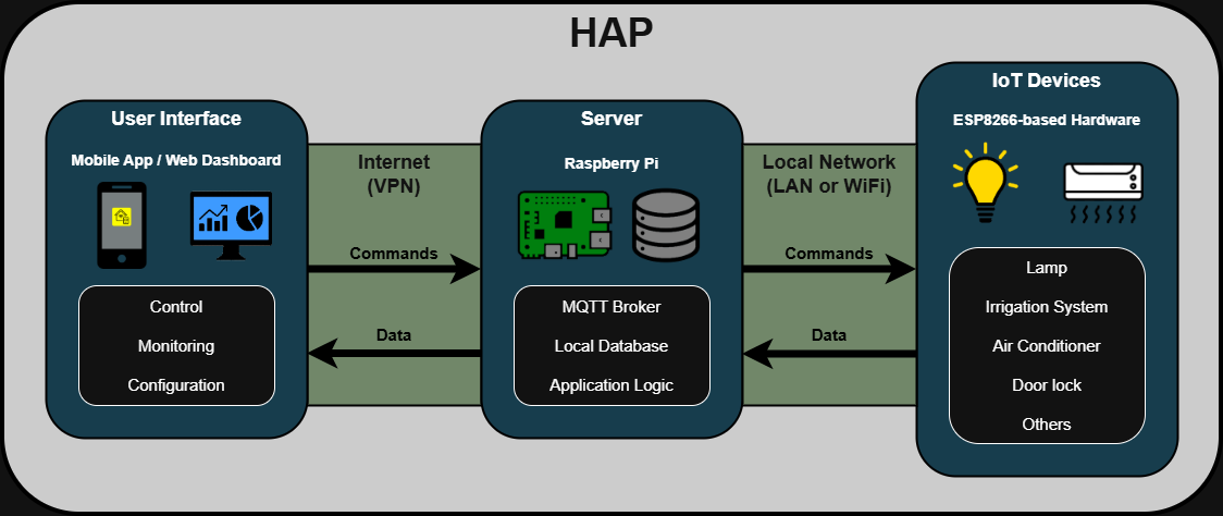
The platform follows a layered architecture:
Remote access is secured using a VPN, allowing the system to remain fully functional without relying on external cloud services.
hap/
├── docs/       # Documentation, diagrams, images
├── firmware/   # ESP8266 firmware for IoT modules
├── hardware/   # PCB designs, schematics, manufacturing files
├── mobile/     # Android application
├── server/     # Core server logic and services
└── README.mdInstall a lightweight Raspberry Pi OS:
Update the system:
sudo apt update
sudo apt upgrade -ysudo apt install git -ygit clone https://github.com/AlanCarvalhoEE/hap.gitcd hapcp server/scripts/credentials_example.py server/scripts/credentials.py
nano server/scripts/credentials.pycd setup
chmod +x setup.sh
./setup.shThe script will install all the needed packages, dependencies and services.
Configure Mosquitto:
sudo nano /etc/mosquitto/mosquitto.conflistener 1883
allow_anonymous truesudo systemctl restart mosquittosudo zerotier-cli join <network_id>After joining, the device must be allowed on the ZeroTier network dashboard.
Reboot the Raspberry Pi:
sudo reboot nowPlanned improvements:
This project is currently intended for personal and educational use. Licensing details may be defined in the future.
| Qty | Value | Footprint | References |
|---|---|---|---|
| 5 | 10k | Alan_Resistor:RES_SMD_0603 | R1, R2, R3, R6, R12 |
| 2 | 10uF | Alan_Capacitor:CAP_SMD_TANTALUM_CASE-A | C3, C4 |
| 2 | 33k | Alan_Resistor:RES_SMD_1206 | R10, R11 |
| 2 | LOGO | LOGO | G***, G*** |
| 1 | 0,25A | Alan_Fuse:FUSEHOLDER_THT_5x20_CLIP | F1 |
| 1 | 0.1uF | Alan_Capacitor:CAP_SMD_CERAMIC_0603 | C5 |
| 1 | 0.1uF | Alan_Capacitor:CAP_THT_CERAMIC_X2_18x6x15 | C1 |
| 1 | 100nF | Alan_Capacitor:CAP_SMD_CERAMIC_0603 | C7 |
| 1 | 100uF | Alan_Capacitor:CAP_SMD_ELEC_6.3x7.7 | C2 |
| 1 | 10k | Alan_Sensor:LDR_5_V | R8 |
| 1 | 12V 5A | Alan_Relay:RELAY_SPDT_FINDER_36.11 | K1 |
| 1 | 2N7002H | Alan_Transistor:SOT-23 | Q1 |
| 1 | 2k2 | Alan_Resistor:RES_SMD_0603 | R4 |
| 1 | 33k | Alan_Resistor:RES_SMD_0603 | R7 |
| 1 | 390R | Alan_Resistor:RES_SMD_0603 | R5 |
| 1 | 470k | Alan_Resistor:RES_SMD_1206 | R9 |
| 1 | 47nF | Alan_Capacitor:CAP_THT_CERAMIC_X2_13x5x11_P10 | C6 |
| 1 | 600R | Alan_Inductor:BEAD_SMD_1206 | L1 |
| 1 | AMS1117-3.3 | Alan_IC:SOT-223-3_TAB2 | U1 |
| 1 | CONN_TERMINAL-BLOCK_5P_P5.08 | Alan_Connector:CONN_TERMINAL-BLOCK_5P_P5.08 | J1 |
| 1 | Conn_01x03_Socket | Alan_Connector:CONN_PIN-HEADER_1x03_V | J3 |
| 1 | Conn_01x06_Socket | Alan_Connector:CONN_SOCKET-HEADER_1x06_V | J2 |
| 1 | ESP-12E | Alan_Module:MOD_ESP-12E | U2 |
| 1 | H11AA1 | Alan_IC:SMDIP-6_7.62 | U4 |
| 1 | HLK-PM12 | Alan_Module:HILINK_HLK-PMxx | PS1 |
| 1 | LED | Alan_LED:LED_SMD_0603 | D1 |
| 1 | LOGO | Alan_Label:LABEL_ELECTRIC_SHOCK_RISK_10x10 | G*** |
| 1 | PC817 | Alan_IC:SMDIP-4_7.62 | U3 |
| 1 | S1A | Alan_Diode:DIODE_SMD_SMA | D2 |
The 36 most common of 40 parts.


Arhamee/hardware-portfolio
Multi-layer PCB designs in KiCad 10 schematic capture to fabrication-ready Gerbers. High-speed routing, BGA escape, power electronics.


gabrielfbdiniz/PFC-Boost-STM32
Conversor estático de potência CA/CC com Correção Ativa do Fator de Potência (Active PFC) na topologia Boost, projetado para elevar a tensão da rede elétrica retificada (127V / 220V AC) para um barramento CC…


mrknockknockgaming-droid/hvac-monitor
Fullscope monitors a home's heat pump or air conditioner continuously, the way a technician would with gauges on it, and tells the contractor and the homeowner when something is going wrong, before it becomes a no-cool…

So11Deo6loria/bsidesPRSun
Please note that if the badge is running consistently, the battery life will be limited.
It measures 46 × 77 mm and has 2 copper layers, 1.6 mm thick.
40 parts, built around the ESP-12E, HLK-PM12, AMS1117-3.3 and H11AA1. The full list of its parts is on this page, with links to each part's symbol and footprint where PCBKit's library has them.
From the AlanCarvalhoEE/hap repository on GitHub, at the commit this page was made from: the board is hardware/on_off_module_x1/on_off_module_x1.kicad_pcb and its schematic hardware/on_off_module_x1/on_off_module_x1.kicad_sch. PCBKit opens the board in the browser, with nothing to install.
Its repository states no licence, so its author keeps all rights: ask AlanCarvalhoEE before reusing the design.