

2 layers132.1 × 45.7 mm
IPoS
peterheinrich/InternetOverSpaghetti
Transmitting IP packages over a pair of spaghetti thus demonstrating how media independent IP really is.
42 parts342

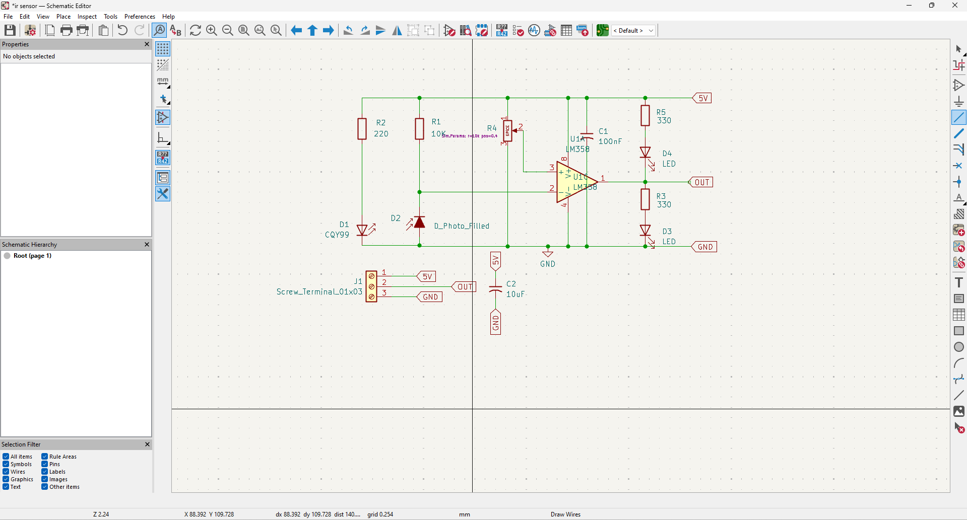
Custom IR obstacle detection sensor PCB designed using KiCad.
Ir sensor is an open-source printed circuit board by Agilan74, from the Agilan74/IR-Obstacle-Detection-Sensor-PCB repository on GitHub. It is a 2-layer board of 60 × 36.5 mm with 17 parts on 8 nets, routed with 71 tracks and 3 vias.
It is built around the LM358. Its parts include 5 resistors, 4 diodes, 2 capacitors, 1 IC and 1 connector. It belongs with the sensors and measurement and home automation and IoT boards of this library.
A custom-designed IR obstacle detection sensor PCB developed using KiCad and LM358 operational amplifier for robotics, automation, and STEM applications.
This project is a custom IR Obstacle Detection Sensor PCB designed using KiCad.
The IR LED continuously emits infrared light.
When an object comes close to the sensor, the emitted infrared light reflects back and is detected by the photodiode.
The LM358 operational amplifier processes this signal and produces an output indicating the presence of an object.
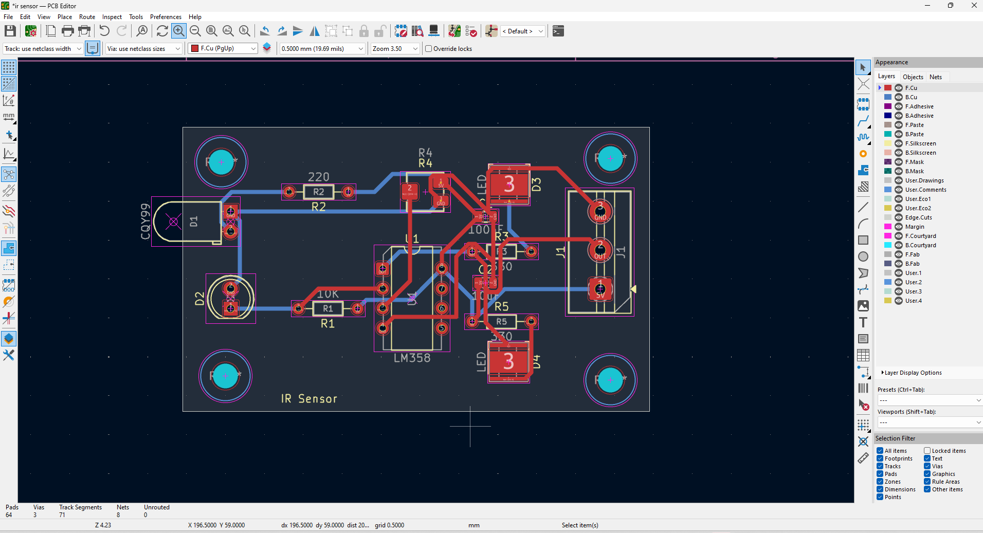
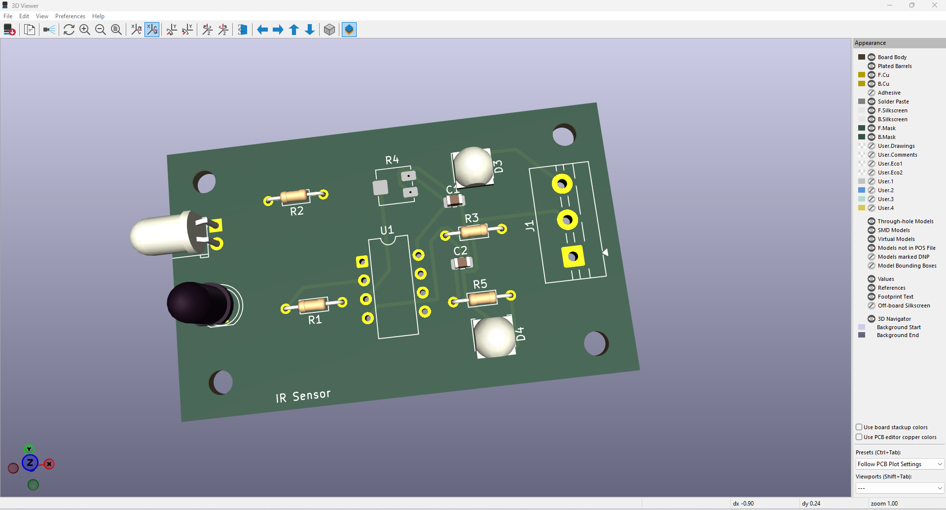
Gerber and drill files required for PCB fabrication are available in the Gerber_Files directory.
Agilan Loganathan
| Qty | Value | Footprint | References |
|---|---|---|---|
| 2 | 330 | Resistor_THT:R_Axial_DIN0204_L3.6mm_D1.6mm_P7.62mm_Horizontal | R3, R5 |
| 2 | LED | LED_SMD:LED_Cree-XHP50_3V_HighDensity | D3, D4 |
| 1 | 100nF | Capacitor_SMD:C_0805_2012Metric | C1 |
| 1 | 10K | Resistor_THT:R_Axial_DIN0204_L3.6mm_D1.6mm_P7.62mm_Horizontal | R1 |
| 1 | 10uF | Capacitor_SMD:C_0805_2012Metric | C2 |
| 1 | 220 | Resistor_THT:R_Axial_DIN0204_L3.6mm_D1.6mm_P7.62mm_Horizontal | R2 |
| 1 | CQY99 | LED_THT:LED_D5.0mm_Horizontal_O1.27mm_Z3.0mm_Clear | D1 |
| 1 | D_Photo_Filled | LED_THT:LED_D5.0mm_IRBlack | D2 |
| 1 | LM358 | Package_DIP:CERDIP-8_W7.62mm_SideBrazed | U1 |
| 1 | Potentiometer | Potentiometer_SMD:Potentiometer_Bourns_3214J_Horizontal | R4 |
| 1 | Screw_Terminal_01x03 | TerminalBlock:TerminalBlock_MaiXu_MX126-5.0-03P_1x03_P5.00mm | J1 |
The 13 most common of 17 parts.
peterheinrich/InternetOverSpaghetti
Transmitting IP packages over a pair of spaghetti thus demonstrating how media independent IP really is.

zmaker/arduino_cookbook
gli sketch del nuovo progetto Arduino Cookbook e dei video di YouTube

profdc9/RFBitBanger
A QRP digital transceiver created from readily available parts for off-the-grid maintenance


tvlad1234/pillScopePlus
Oscilloscope based around the STM32F401 Black Pill and a color LCD screen


starlightk7/OpenSFC
OSHW Reproduction Parts related to the Super Famicom / Super Nintendo game console

It measures 60 × 36.5 mm and has 2 copper layers, 1.6 mm thick.
17 parts, built around the LM358. The full list of its parts is on this page, with links to each part's symbol and footprint where PCBKit's library has them.
From the Agilan74/IR-Obstacle-Detection-Sensor-PCB repository on GitHub, at the commit this page was made from: the board is ir sensor.kicad_pcb and its schematic ir sensor.kicad_sch. PCBKit opens the board in the browser, with nothing to install.
Its repository states no licence, so its author keeps all rights: ask Agilan74 before reusing the design.