
2 layers22 × 40 mm
QFN Board
ADBeta/CH32V003_Breakout_Boards
A Collection of Breakout Boards for the CH32V003 MCU, in many footprints, for many usecases
13 parts3MIT

 ADBeta/CH32V003_Breakout_Boards3
A Collection of Breakout Boards for the CH32V003 MCU, in many footprints, for many usecases
TSSOP Board is an open-source printed circuit board by ADBeta, from the ADBeta/CH32V003_Breakout_Boards repository on GitHub, published under the MIT licence. It is a 2-layer board of 16.8 × 41.5 mm with 16 parts on 28 nets, routed with 161 tracks and 19 vias.
It is built around the AP2112K-3.3. Its parts include 4 connectors, 3 capacitors, 3 resistors, 2 ICs and 1 switch. It belongs with the RISC-V boards of this library.
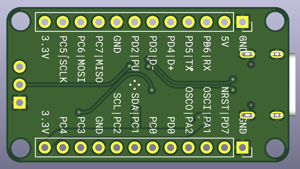
A Breakout Board for the QFN Variant of the CH32V003, with pins broken out for I2C, SPI, UART, USB, and with a USB-C Connector, and an NRST Button.
This Board has been designed with generic and minimal parts, to make the
production and assembly of these boards easy and cheap for novices, looking to
get into the hobby and/or use the CH32V003 Chips
NOTE: If using the USB Pins for other purposes, please keep in mind that USB_DM and USB_PU are connected togehter with a 1.5K resistor. Remove this if needed
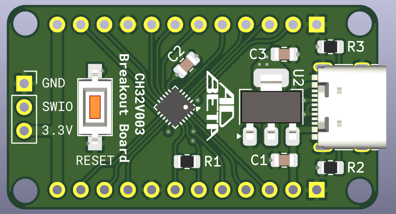
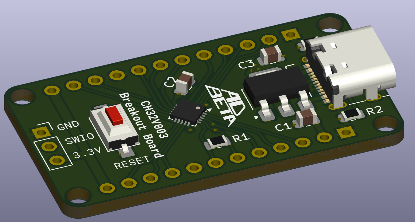
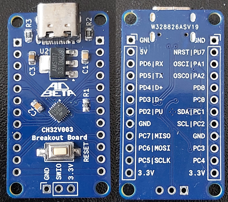
J2 Generic 16 Pin USB C Connector
J1 3 x 2.54mm (0.1") Pin Header
J3 12 x 2.54mm (0.1") Pin Header
J4 12 x 2.54mm (0.1") Pin Header
R1 0805 1.5K Resistor
R2 0805 5.1K Resistor (Can leave unpopulated, or use 5K - 22K instead)
R3 0805 5.1K Resistor (Can leave unpopulated, or use 5K - 22K instead)
C1 0805 100nF Capacitor
C2 0805 100nF Capacitor
C3 0805 10uF Capacitor (Can leave unpopulated, or use 100nF instead)
SW1 Generic 6mm x 3mm Tactile Button
U1 QFN20 0.4mm Pitch CH32V003
U2 AMS1117 3.3c Voltage Regulator
USB
Pullup PD2D- PD3D+ PD4SPI
SCLK PC5MOSI PC6MISO PC7I2C
SDA PC1SCL PC2UART
TX PD5RX PD6The PCB is 22mm x 40mm, with 4 x 2.6mm holes in a rectangle pattern; 18mm x 36mm.
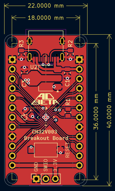
Copyright (c) ADBeta 2024
| Qty | Value | Footprint | References |
|---|---|---|---|
| 2 | 100nF | Capacitor_SMD:C_0805_2012Metric | C1, C3 |
| 2 | 5K1 | Resistor_SMD:R_0805_2012Metric | R1, R2 |
| 1 | 10uF | Capacitor_SMD:C_0805_2012Metric | C2 |
| 1 | 1K5 | Resistor_SMD:R_0805_2012Metric | R3 |
| 1 | AP2112K-3.3 | Package_TO_SOT_SMD:SOT-23-5 | U1 |
| 1 | CH32V003FxPx | Package_SO:TSSOP-20_4.4x6.5mm_P0.65mm | U2 |
| 1 | HEADER_LEFT | Footprints:PinSocket_1x11_P2.54mm_No_Silk | J2 |
| 1 | HEADER_RIGHT | Footprints:PinSocket_1x11_P2.54mm_No_Silk | J3 |
| 1 | JMP_USB_DM | Jumper:SolderJumper-2_P1.3mm_Bridged_RoundedPad1.0x1.5mm | JP2 |
| 1 | JMP_USB_DP | Jumper:SolderJumper-2_P1.3mm_Bridged_RoundedPad1.0x1.5mm | JP3 |
| 1 | JMP_VIN_SEL | Jumper:SolderJumper-2_P1.3mm_Open_RoundedPad1.0x1.5mm | JP1 |
| 1 | NRST | Button_Switch_SMD:SW_Push_SPST_NO_Alps_SKRK | SW1 |
| 1 | PROG_HEADER | Footprints:PinSocket_1x03_P2.54mm_No_Silk | J4 |
| 1 | USB_C | Connector_USB:USB_C_Receptacle_G-Switch_GT-USB-7010ASV | J1 |
ADBeta/CH32V003_Breakout_Boards
A Collection of Breakout Boards for the CH32V003 MCU, in many footprints, for many usecases

FrameworkComputer/ExpansionCards
Reference designs and documentation to create Expansion Cards for the Framework Laptop


DDeGonge/OS-ARM
This arm is not industrial and it will not be fast, but that is not my goal. But it will hopefully be a very nice looking arm fully capable of 6dof motion, cheap enough to keep it accessable but capable enough to…


It measures 16.8 × 41.5 mm and has 2 copper layers, 1.6 mm thick.
16 parts, built around the AP2112K-3.3. The full list of its parts is on this page, with links to each part's symbol and footprint where PCBKit's library has them.
From the ADBeta/CH32V003_Breakout_Boards repository on GitHub, at the commit this page was made from: the board is TSSOP_Board/TSSOP_Board.kicad_pcb and its schematic QFN_Board/QFN_Board.kicad_sch. PCBKit opens the board in the browser, with nothing to install.
Its repository publishes it under the MIT licence: you may reuse it on that licence's terms (keep the author's notice, and for a copyleft licence share your changes alike).