2 layers50 × 40 mm

 6r1d/enhancing_boards2
My place to store and improve KiCad boards and schematics
PCM5102A is an open-source printed circuit board by 6r1d, from the 6r1d/enhancing_boards repository on GitHub, published under the MIT licence. It is a 2-layer board of 65.6 × 34.1 mm with 38 parts on 38 nets, routed with 279 tracks and 18 vias.
It is built around the TPA6132A2RTE, TJ9198GSF5-3.3D and PCM5102PW. Its parts include 4 capacitors, 4 ICs, 1 diode and 1 connector. It belongs with the interfaces and adapters and microcontroller boards boards of this library.


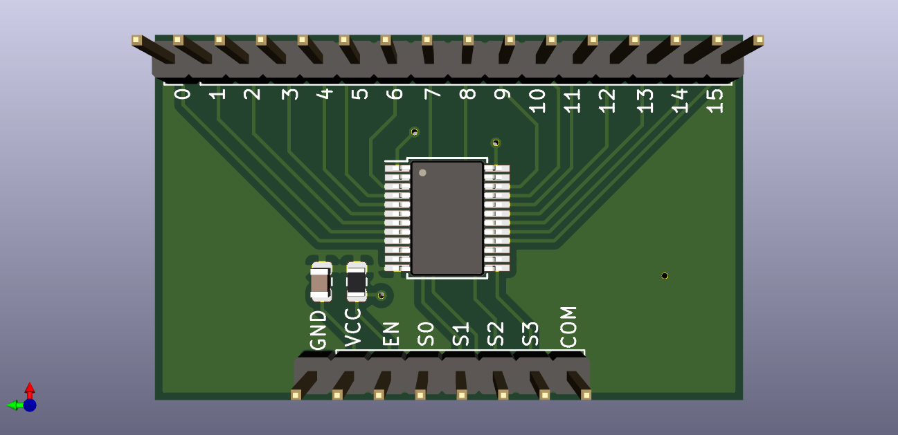
If you have never used multiplexors, this IC connects a single pin to one of the several outputs, where an output pin is picked using other digital input pins. Think railroad switch, but for electronics, not for railroad.
I had some of those mux board around for quite some time and they are working nicely with Arduino, so I decided to make a copy of a very short schematic and to make my own layout. Why? Well, as usual, to test and be sure I can use them in my own devices later.
| Qty | Value | Footprint | References |
|---|---|---|---|
| 5 | 220 / 330 | Resistor_SMD:R_0603_1608Metric | R_AMP_EN_2, R_BCK_1, R_DIN_1, R_LCK_1, R_SCK_1 |
| 2 | TJ9198GSF5-3.3D | Package_TO_SOT_SMD:SOT-23-5 | U2, U3 |
| 2 | 0.01 | Capacitor_SMD:C_0603_1608Metric | C6, C9 |
| 2 | 0.1 uF | Capacitor_SMD:C_0603_1608Metric | C_DVDD1, C_LDOO1 |
| 2 | 1 uF | Capacitor_SMD:C_0603_1608Metric | C_AL1, C_HPVSS_1 |
| 2 | 1uF | Capacitor_SMD:C_0603_1608Metric | C_AR1, CP_P_N1 |
| 2 | 2.2 | Capacitor_SMD:C_0603_1608Metric | C5, C8 |
| 2 | 2.2 uF | Capacitor_SMD:C_0603_1608Metric | C_AMP_VDD1, C_HPVDD1 |
| 2 | 2.2nF | Capacitor_SMD:C_0603_1608Metric | C_DAC_L1, C_DAC_R1 |
| 2 | 2.2uF | Capacitor_SMD:C_0603_1608Metric | C_PCM_CAPS_1, C_PCM_VNEG_1 |
| 2 | 471 | Resistor_SMD:R_0603_1608Metric | R_DAC_L1, R_DAC_R1 |
| 2 | Conn_01x02 | Connector_PinHeader_2.54mm:PinHeader_1x02_P2.54mm_Vertical | J_SCK1, J_XSMT1 |
| 2 | Conn_02x03_Odd_Even | Connector_PinHeader_2.54mm:PinHeader_2x03_P2.54mm_Vertical | J_DAC_OUT_1, J_JMP1 |
| 1 | 0.1u | Capacitor_SMD:C_0603_1608Metric | C_AVDD_2 |
| 1 | 0.1uF | Capacitor_SMD:C_0603_1608Metric | C_CPGND1 |
| 1 | 10u | Capacitor_SMD:C_0603_1608Metric | C_AVDD_1 |
| 1 | 1k | Resistor_SMD:R_0603_1608Metric | R_LED1 |
| 1 | Conn_01x03 | Connector_PinHeader_2.54mm:PinHeader_1x03_P2.54mm_Vertical | J_SND_OUT1 |
| 1 | Conn_01x06 | Connector_PinHeader_2.54mm:PinHeader_1x06_P2.54mm_Vertical | J1 |
| 1 | LED | LED_SMD:LED_0603_1608Metric_Castellated | D1 |
| 1 | PCM5102 | Package_SO:TSSOP-20_4.4x6.5mm_P0.65mm | U1 |
| 1 | TPA6132A2RTE | Package_DFN_QFN:WQFN-16-1EP_3x3mm_P0.5mm_EP1.6x1.6mm_ThermalVias | U4 |

6r1d/enhancing_boards
My place to store and improve KiCad boards and schematics


aaravjhamb/openIEMA
A high quality open source In Ear Monitor Amplifier!! (IEMA for short)

gelotek-com/Anki-In-Hardware
Building a physical flashcard device inspired by Anki and spaced repetition.

Hasnat4763/Akash-Chowa-DX
Akash Chowa DX is a SW/MW/LW receiver designed based on the Si4735 Radio receiver IC paired with the RP2040 Zero Dev board.

NZX37/ESP32Musicplayer
A rechargeable music player built around an ESP32-S3. The design is intended to play music stored on a microSD card and send stereo audio to standard headphones through a 3.5 mm jack.


Ace6Rings/MUSIC-PLAYER
Why did I build something like this? Well, I am sick and tired of buying spotify premium every month. I looked for mp3 players online but nearly all of them have the same flaw(s).

baba2712/smart-helmet-with-anc
An industrial safety helmet with hybrid active noise cancellation (feed-forward + adaptive feedback FxLMS) on an STM32H743.
It measures 65.6 × 34.1 mm and has 2 copper layers, 1.6 mm thick.
38 parts, built around the TPA6132A2RTE, TJ9198GSF5-3.3D and PCM5102PW. The full list of its parts is on this page, with links to each part's symbol and footprint where PCBKit's library has them.
From the 6r1d/enhancing_boards repository on GitHub, at the commit this page was made from: the board is PCM5102A/PCM5102A.kicad_pcb. PCBKit opens the board in the browser, with nothing to install.
Its repository publishes it under the MIT licence: you may reuse it on that licence's terms (keep the author's notice, and for a copyleft licence share your changes alike).