

2 layers45.7 × 31.8 mm
LEDx16 board
tardate/LittleArduinoProjects
a collection of "Little Electronic & Arduino Projects", most involving electronics or an Arduino in one way or another!
36 parts803MIT

 3top1a/modelk2
Modelk: BLE Wireless IBM Model M Replacement Controller
Modelk is an open-source printed circuit board by 3top1a, from the 3top1a/modelk repository on GitHub. It is a 2-layer board of 150 × 38 mm with 52 parts on 72 nets, routed with 278 tracks and 0 vias.
It is built around the 74HC595. Its parts include 20 diodes, 8 connectors, 4 ICs, 3 resistors and 1 switch. It belongs with the keyboards and input and radio and wireless boards and the nRF52 and nRF5x boards of this library.
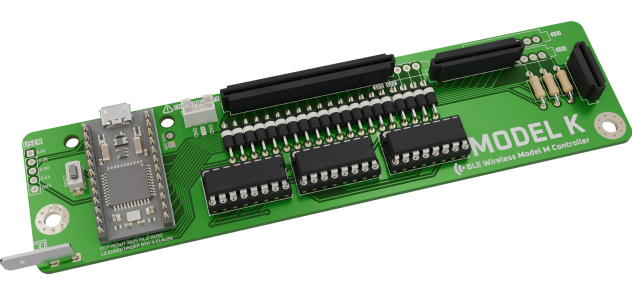 Render may be of an outdated version, the images below are from a CI/CD render and are always up-to-date. Only compatible with nice!nano, other MCUs won't work


Modelk is a custom replacement controller designed to add wireless Bluetooth Low Energy functionality to classic IBM Model M keyboards. This drop-in controller lets you convert your vintage buckling spring keyboard to wireless without permanent modification, preserving the original controller.
The PCB is designed in KiCad 9. This repository has a CI/CD pipeline that automatically renders the schematic into a PDF/SVG and generates gerbers for JLCPCB and PCBWAY.
See the automatically generated iBOM (you will need to download the .html file and open it in your browser for now).
For a full assembly, you will need:
Your keyboard might contain 16+12 or 16+8+4 connectors, make sure you order the ones you need! The board supports both of them.
You will need:
Start with a blank PCB and solder the 16 pin connector.
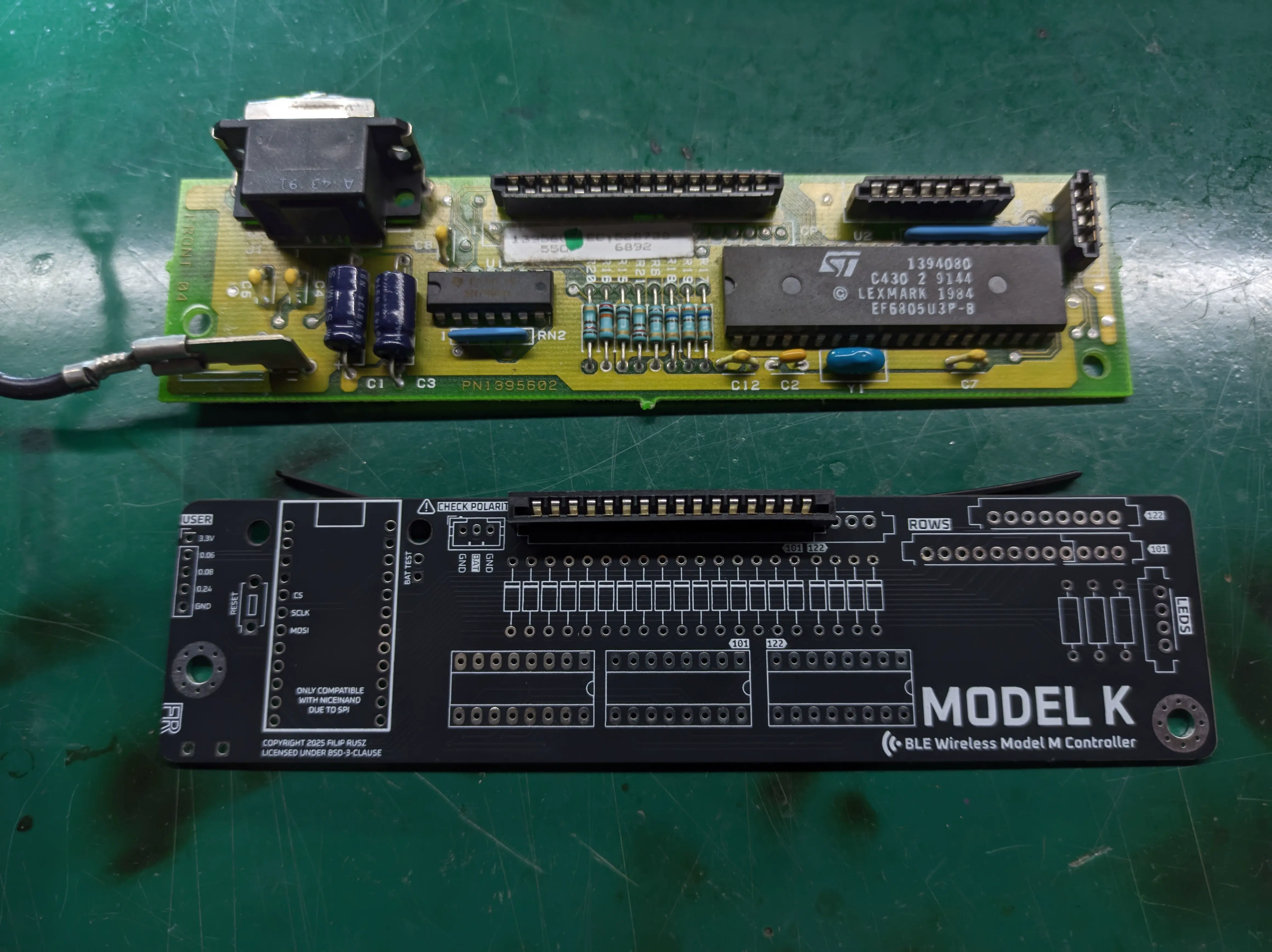
On the bottom you can see the board I am assembling (revision 0.10), and on the top you can see the original controller that came with my keyboard. Because I am using Connfly connectors and not the original TE Trio-mate, I need to rotate them 180° as they work differently.
[!IMPORTANT] If you are using Connfly connectors, make sure to rotate them 180°! This sounds counter-intuitive, but your board will not work otherwise!
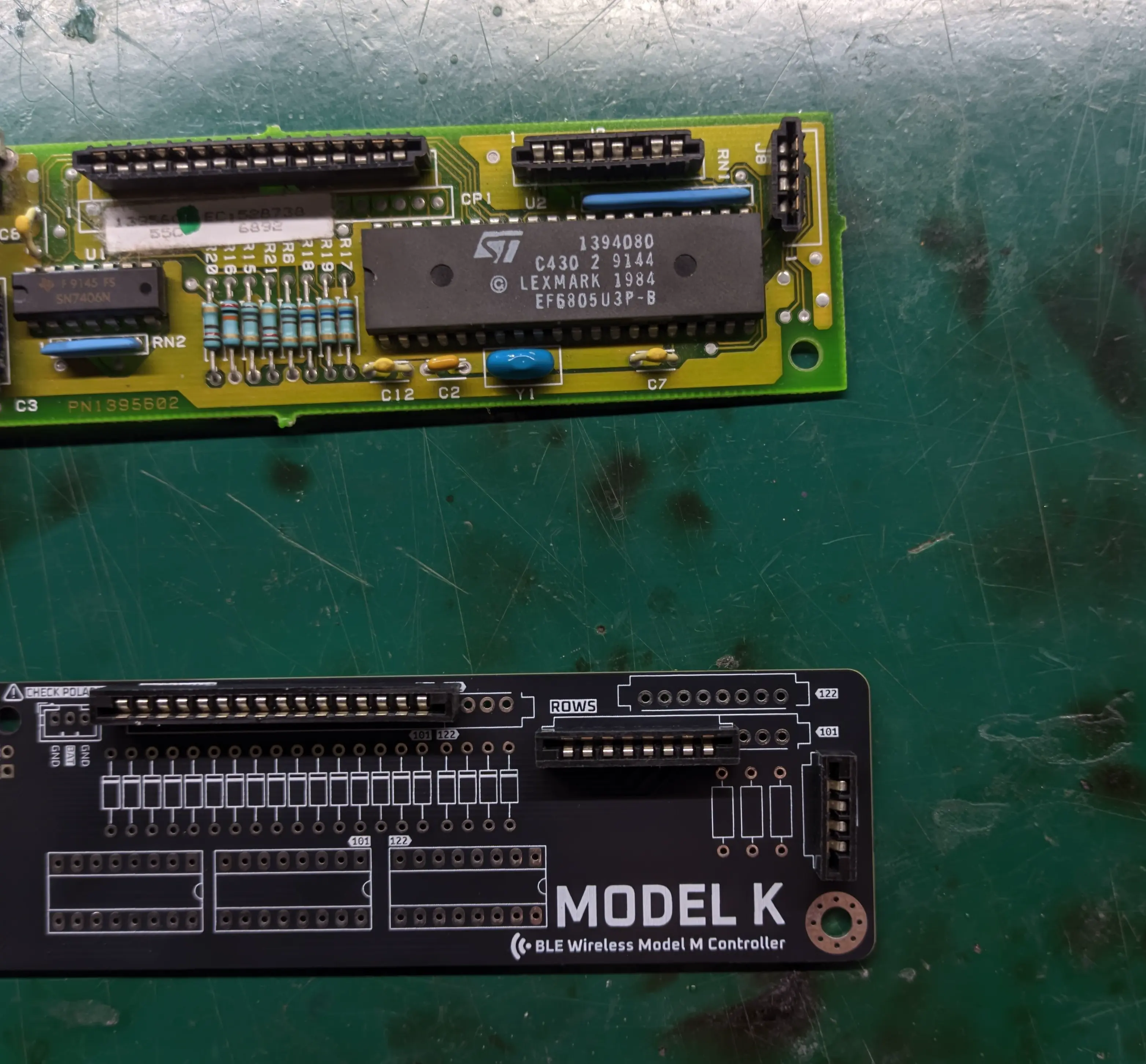
As my keyboard comes with 16+8+4 connectors, I will solder the appropriate connectors, also rotated just like the 16 pin one.
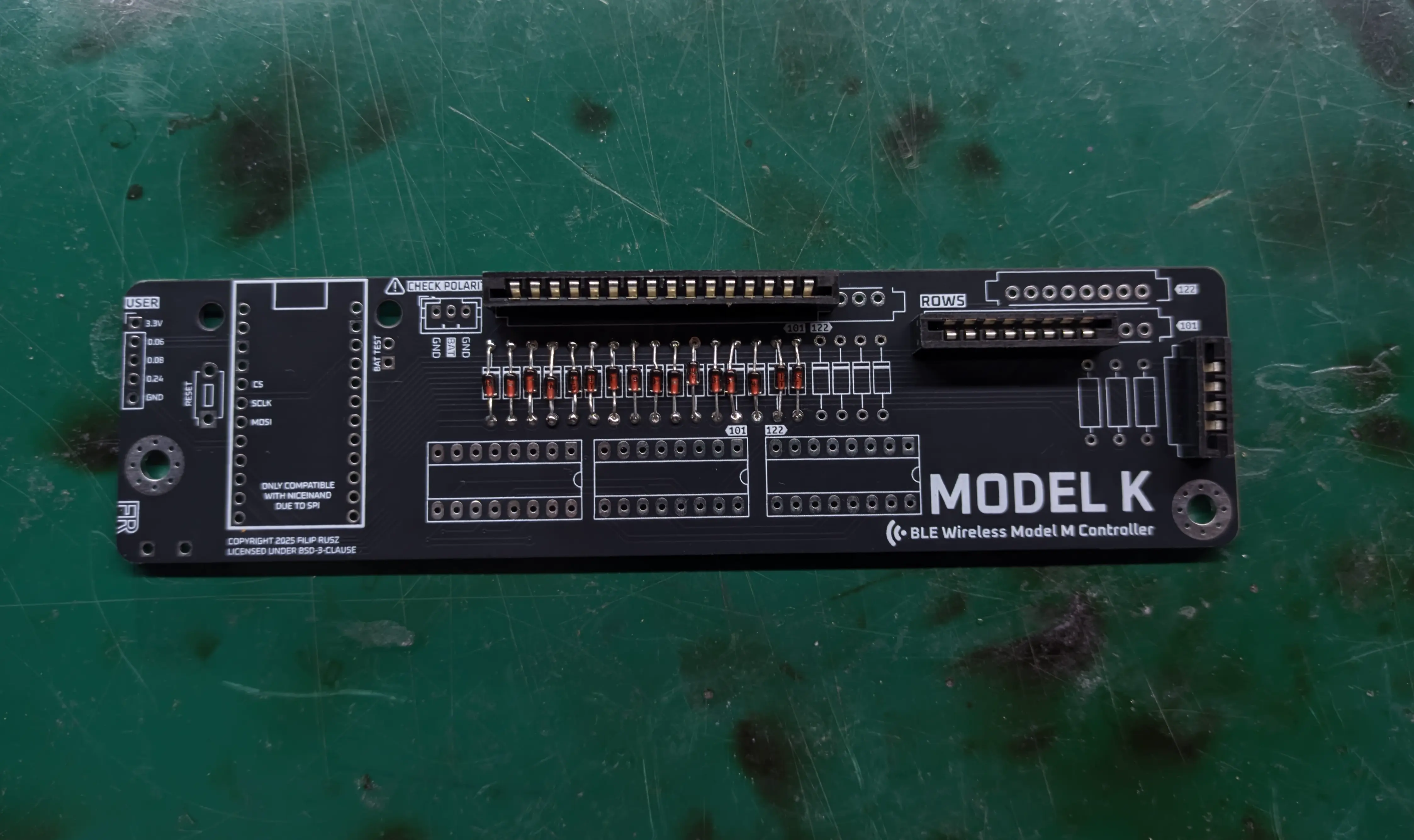
Next up are the diodes, as I have a 101-key keyboard, I will only populate the 16 left-most diodes. Pay attention to the orientation of the diodes, the black strip has to be on top, as indicated on the silkscreen.
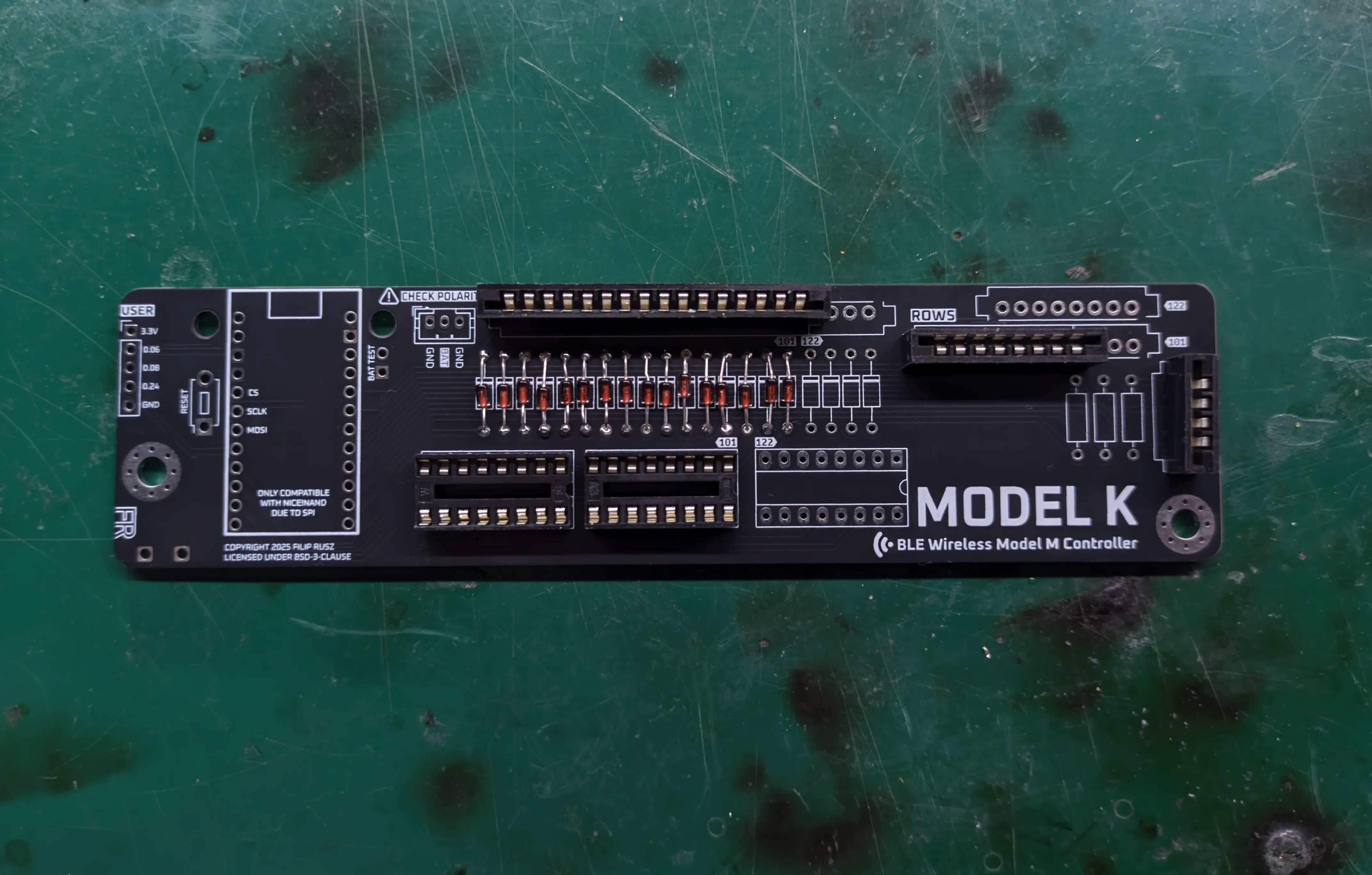
Then the IC sockets, orientation again indicated on the silkscreen (don't forget to populate them!)
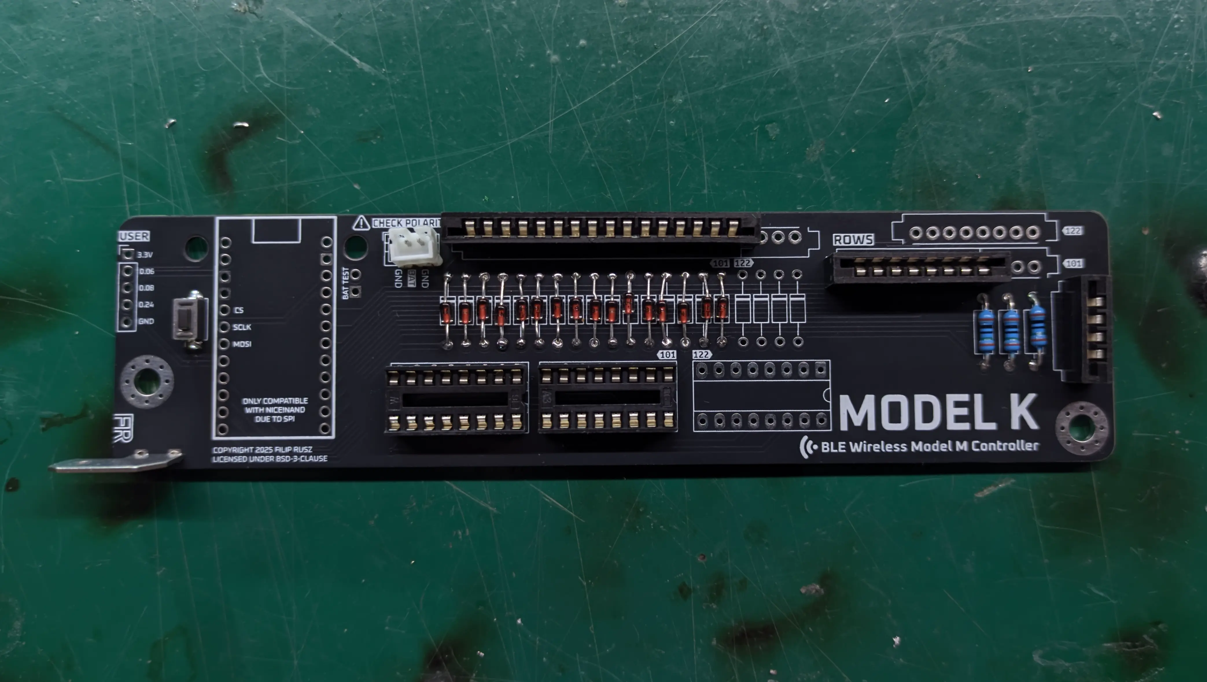
I will skip a bit here, and solder (from left to right) the Faston grounding mount, reset switch, battery connector and resistors. Just be careful soldering the Faston mount, it will get hot.
[!CAUTION] Quadruple check the orientation of the battery connector! The nice!nano doesn't have reverse polarity protection and you will destroy it otherwise.
All that is left is to solder the low profile sockets, solder pins to the nice!nano (see official guide), and populate the ICs.
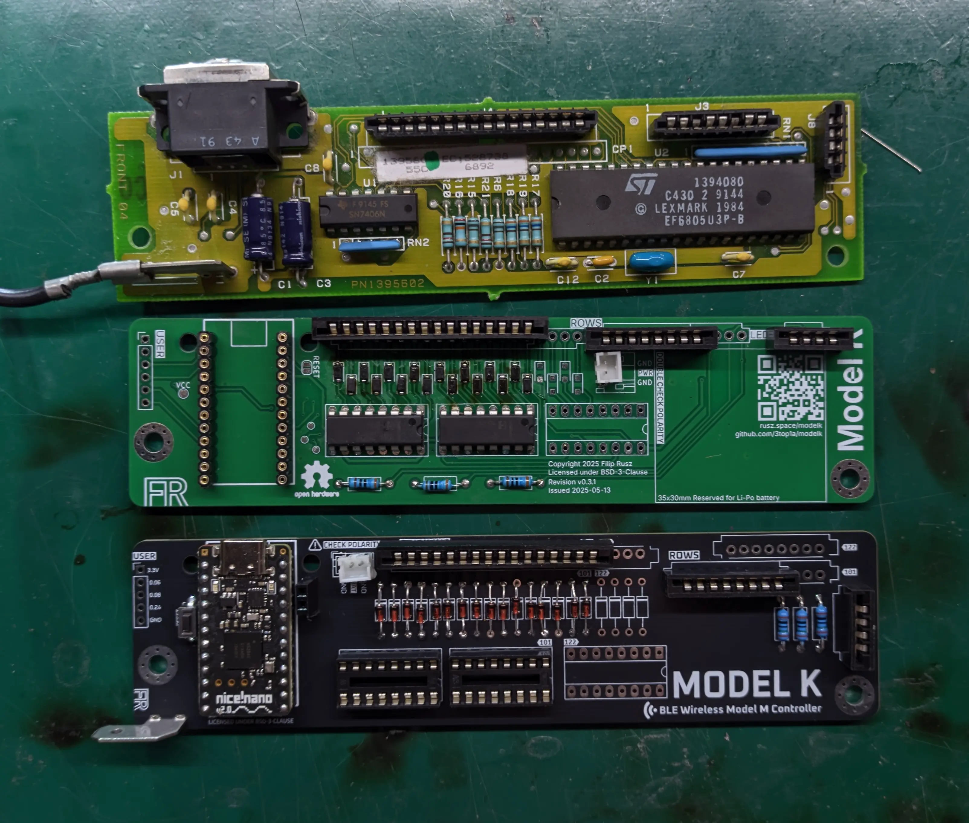
Here you can see the finished board (without ICs, I forgot and spent 10 minutes debugging SPI because of it), a previous iteration (revision 0.3.1) and the original controller.
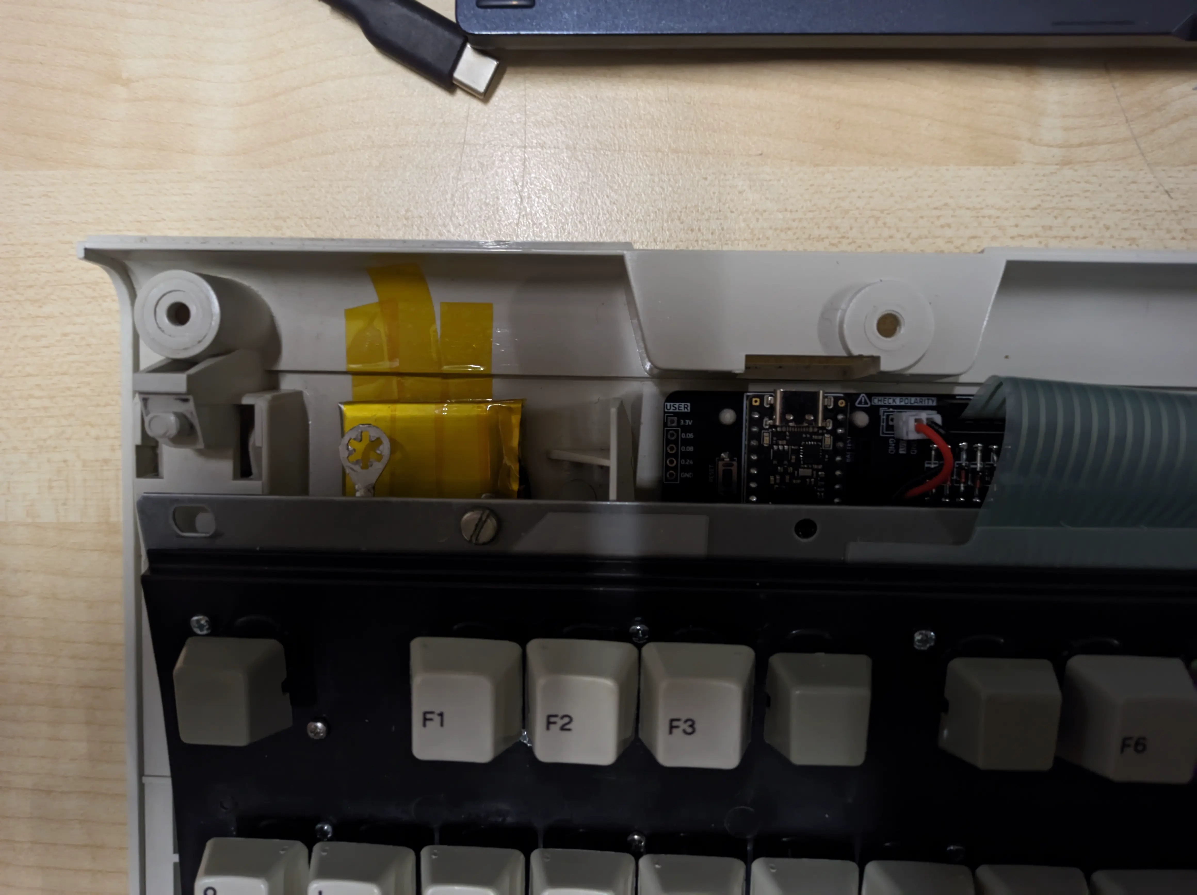
Now you just need to put it into the keyboard, secure the battery with kapton tape, and mount the original grounding wire.
For now, see the modelk-zmk repository for the ZMK firmware. Might get merged into this repository.
Installation:
By default, right alt switches to a function layer, where escape toggles USB/BT and F1-F3 toggles BT profiles, F4 clears the current BT profile, F6-F8 controls multimedia, Print Screen unlocks ZMK Studio and Pause reboots into bootloader for updating firmware. You can, of course, completely redesign the layout.
Huge kudos go to John Hawthorn for his Model H controller that inspired this project. This repo started as a fork, but now doesn't share any files.
| Qty | Value | Footprint | References |
|---|---|---|---|
| 20 | D_Small | Library:DO-35 smaller | D1, D2, D3, D4, D5, D10, D11, D12, D13, D14, D15, D16, D17, D18, D19, D20 +4 |
| 4 | G*** | kibuzzard-684FF45F | kibuzzard-684FF45F, kibuzzard-684FF45F, kibuzzard-684FF45F, kibuzzard-684FF45F |
| 3 | 150 | Resistor_THT:R_Axial_DIN0207_L6.3mm_D2.5mm_P10.16mm_Horizontal | R1, R2, R3 |
| 3 | 74HC595 | Library:DIP-16-74HC595 | U2, U3, U4 |
| 3 | G*** | kibuzzard-684FF466 | kibuzzard-684FF466, kibuzzard-684FF466, kibuzzard-684FF466 |
| 2 | Front | Library:Hole 3.5mm | H3, H4 |
| 2 | Stand | MountingHole:MountingHole_4mm_Pad_Via | H1, H2 |
| 1 | Conn_01x04 | Library:ffc-leds4 | J5 |
| 1 | Conn_01x08 | Library:ffc-rows8 | J6 |
| 1 | Conn_01x12 | Library:ffc-rows12 | J4 |
| 1 | Conn_01x20 | Library:ffc-cols20 | J2 |
| 1 | Dupont for power profiling | Library:BatteryHeader | J8 |
| 1 | Faston PCB mount | Library:faston-mount | J7 |
| 1 | G*** | kibuzzard-684FF5A3 | kibuzzard-684FF5A3 |
| 1 | JST-PH connector | Connector_JST:JST_PH_B3B-PH-K_1x03_P2.00mm_Vertical | J1 |
| 1 | LOGO | Library:LOGO-QR | G*** |
| 1 | LOGO | Library:fr | G*** |
| 1 | SW_reset | Button_Switch_THT:SW_PUSH_1P1T_6x3.5mm_H4.3_APEM_MJTP1243 | SW1 |
| 1 | User exposed | Connector_PinHeader_2.54mm:PinHeader_1x05_P2.54mm_Vertical | J3 |
| 1 | nice_nano | Library:nice_nano | U1 |
The 50 most common of 52 parts.
It measures 150 × 38 mm and has 2 copper layers, 1.6 mm thick.
52 parts, built around the 74HC595. The full list of its parts is on this page, with links to each part's symbol and footprint where PCBKit's library has them.
From the 3top1a/modelk repository on GitHub, at the commit this page was made from: the board is pcb/modelk.kicad_pcb and its schematic pcb/modelk.kicad_sch. PCBKit opens the board in the browser, with nothing to install.
Its repository states no licence, so its author keeps all rights: ask 3top1a before reusing the design.
tardate/LittleArduinoProjects
a collection of "Little Electronic & Arduino Projects", most involving electronics or an Arduino in one way or another!

ChrisChrisLoLo/beyblock20
The magnetic, modular, 20-key macropad that can join together to form an ortholinear board

slu4coder/Minimal-64x4-Home-Computer
My DIY TTL home computer with VGA and PS/2 and 4x the processing power of a Commodore C64 or Apple II.

electroniceel/protoboard
Advanced protoboard layout with 1.27mm pitch for smd parts

TobleMiner/DC-UPS
A small DC UPS, designed to keep small appliances like consumer network equipment running during power outages


