

2 layers43.8 × 31.8 mm
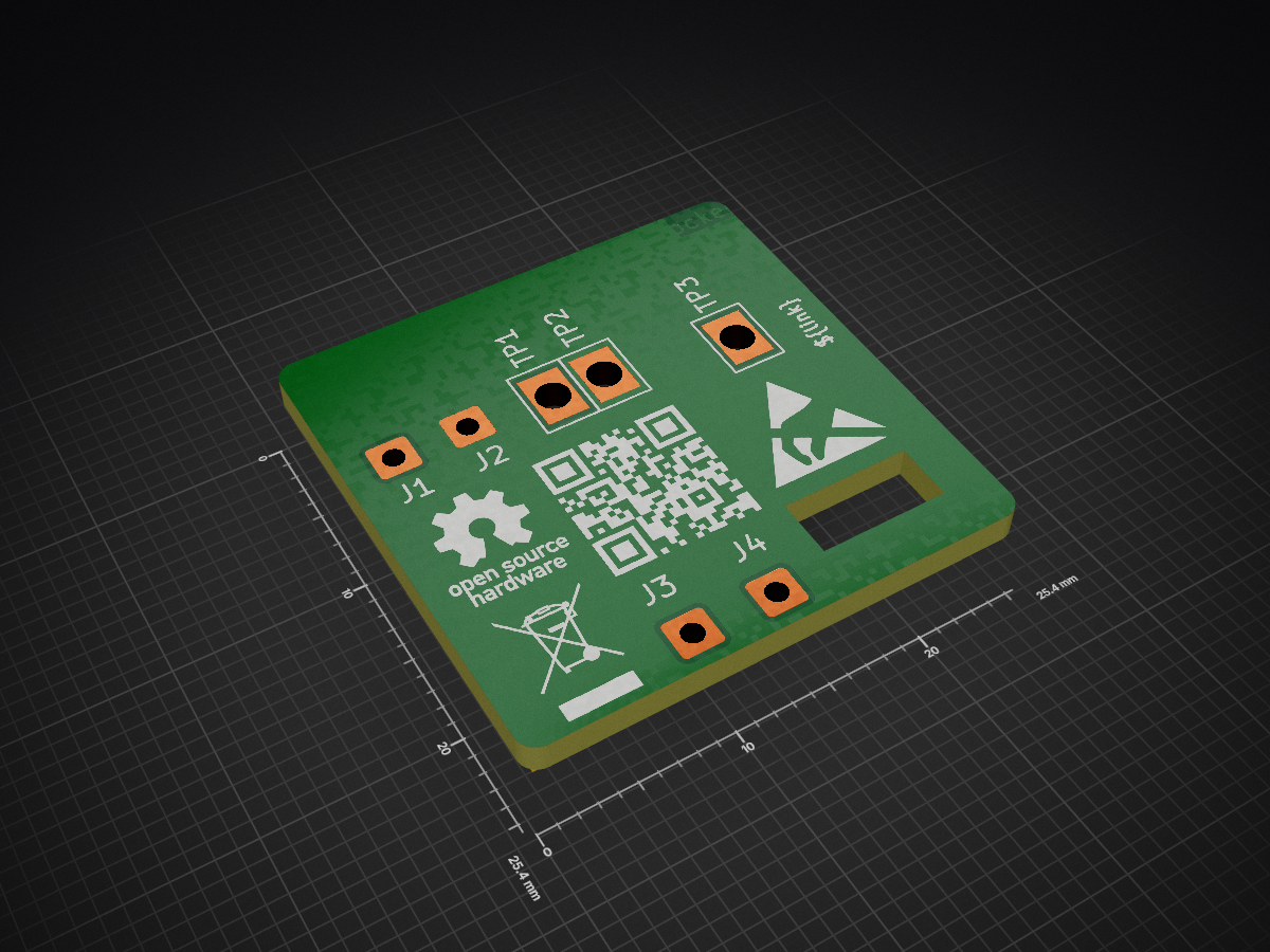
 0x007E/rcc_programmer
Programming platform for RCC
RCC prog is an open-source printed circuit board by 0x007E, from the 0x007E/rcc_programmer repository on GitHub. It is a 2-layer board of 25.4 × 25.4 mm with 21 parts on 16 nets, routed with 24 tracks and 0 vias.
It is built around the FT230XS-R and BAT43. Its parts include 5 capacitors, 4 connectors, 2 resistors, 1 IC and 1 diode.


RCC_programmer - RCC (UPDI) Programmer
The RCC_programmer project is based on a pcb with an FT230XS to program the RCC (RGB LED Color Cube). It either can be programmed with the developed module or with a simple self-made UPDI converter. The deliverd software writes the defined settings with avr-dude over serialupdi onto the ATTiny402.
| Experience | Level |
|---|---|
| Soldering | |
| Mechanical | |
| Software |
| Type | File | Description |
|---|---|---|
| Schematic | pdf / cadlab | Schematic files |
| Board | pdf / cadlab | Board file |
| Drill | Drill file | |
| PCB | zip / tar | KiCAD/Gerber/BoM/Drill files |
| Mechanical | zip / tar | FreeCAD/Housing and PCB (STEP) files |
| Installer | exe | ClickOnce installer (x64) for RCC Programming software |
| Portable | zip / tar | Software (x64) for Programming the RCC |
There are two parts of the hardware. The pcb and the housing of the RCC_programmer. The pcb is created with KiCAD and the housing with FreeCAD . The software is programmed with Visual Studio. All files are built with github actions so that they are ready for a production environment. The housing is printed with a 3D-printer (Dremel 3D40) and the software is build as ClickOnce application that can be installed over a simple setup file and keeps automatically up-to-date.
The circuit board is populated on one side (Top). The best way for soldering the SMD components is within a vapor phase soldering system.


The housing has a tolerance of 0.2mm on each side of the case. So the pcb should fit perfectly in the housing. The tolerance can be modified with FreeCAD in the Parameter Spreadsheet.
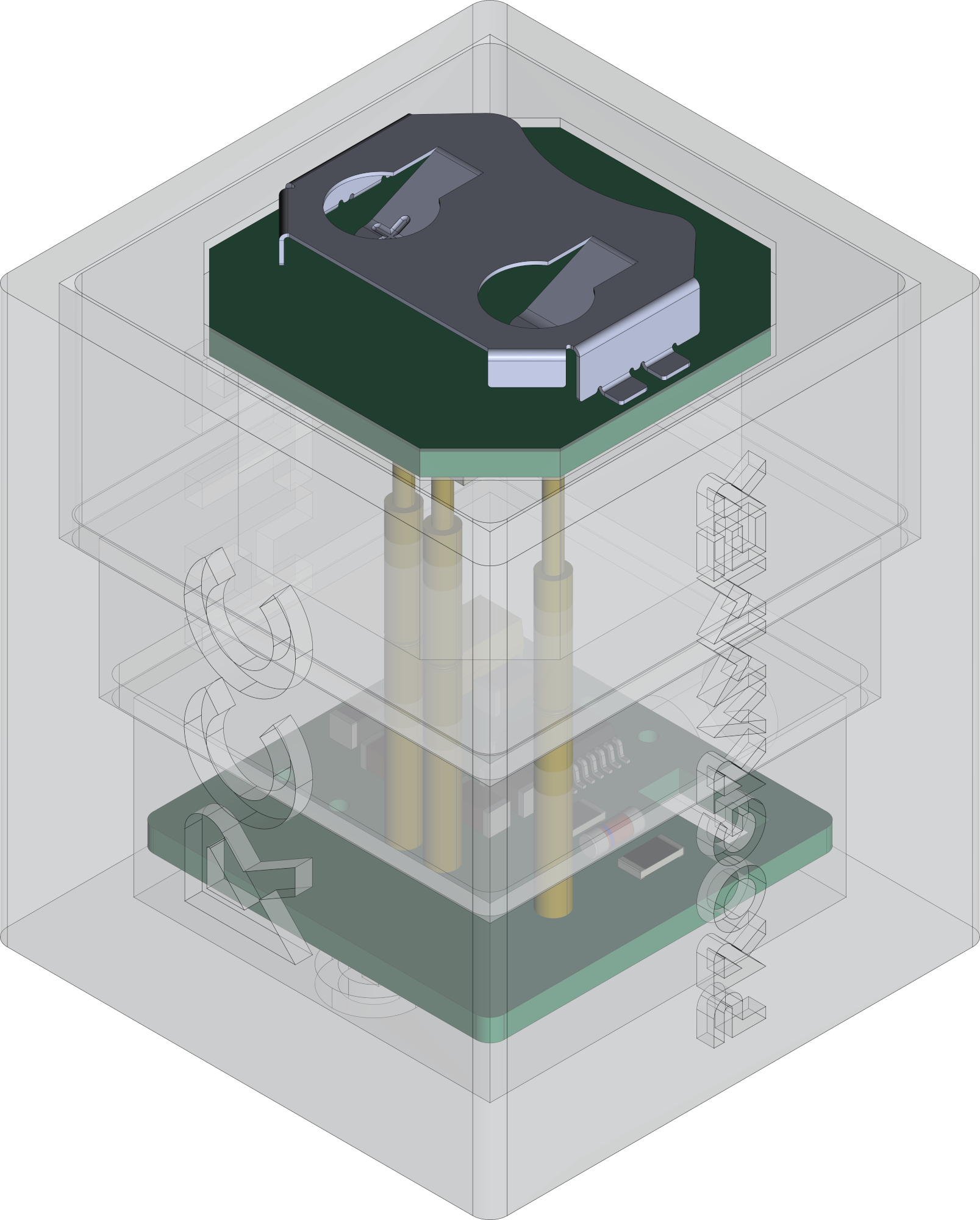
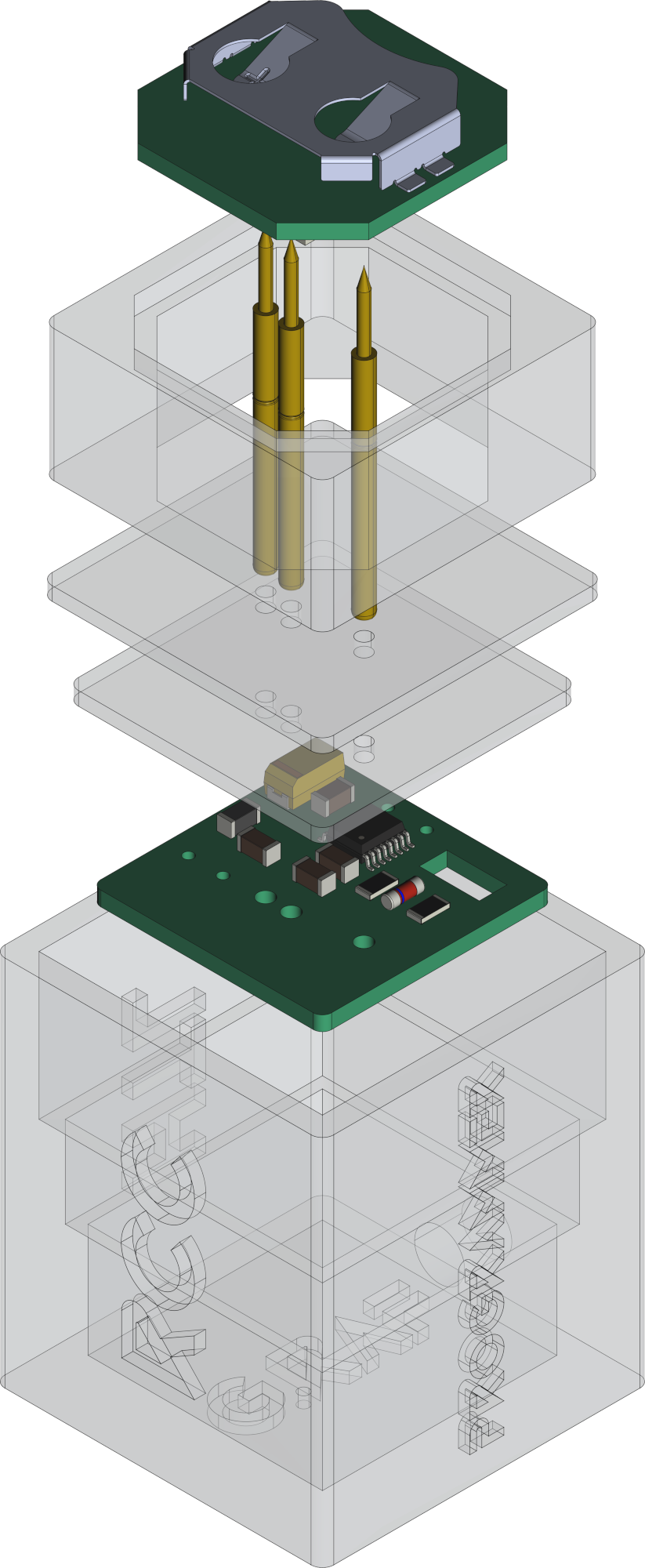
The RCC_programmer is powerd over USB with 5V and uses the internal 3V3 converter of the FT230XS as main programming voltage. The programming software itself uses avr-dude in background and a simple UPDI circuit to program the RCC. It can be programmed over UPDI on TP1. The firmware for the cube can be downloaded in the download section.
#               RCC                     RCC_programmer (Adapter)
#                                     +-------------------------+      +---------------------+
#                                     |          TXD     U  +---+---+  |                     |
#     +---------------------+         |     U     +      S  |  USB  |--+ +-----------------+ |
#     |                     |         |     P    +++     B  +---+---+  | | RCC Programmer  | |
#     |    RCC - Color Cube |         |     D    / \     /      |      | | ~~~~~~~~        | |
#     |                  +--+--+   +--+--+  I    +++     U      |      | | ~~~~~           | |
#     |              VCC | TP3 +---+ VCC |        |      A      |      | | ~~~~~~~~~~~~    | |
#     |              GND | TP2 +---+ GND |  B    +++     R      |      | |                 | |
#     |                  +--+--+   +--+--+  R    | |     T      |      | +-----------------+ |
#     |                     |         |     I    | |            |      |                     |
#     |                  +--+--+   +--+--+  D    +++   +------+ |      | Computer            |
#     |             UPDI | TP1 +---+ PDI +--G-----+    | 3V3  | |      |                     |
#     |                  +--+--+   +--+--+  E    RXD   +------+ |      +---------------------+
#     +---------------------+         +-------------------------+
#| Icon | Description |
|---|---|
 | ClickOnce installable |
The app can be installed as clickonce application that automatically gets updated or run as portable app that need to be updated manually. Both files (setup/portable) are found in the download section.
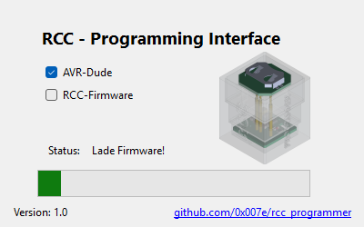
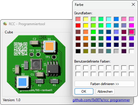
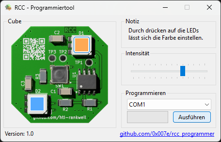
The software loads avr-dude and the current firmware of the RCC from predefined repositories in appsettings.json. By clicking onto the LEDs the color of each LED can be defined. With the intensity trackbar the brightness of the LEDs can be adjusted. To program the RCC the correct selection of the serial port is necessary. By hitting the program button the RCC gets programmed over serialupdi with avr-dude (if the programmer is connected correctly with the RCC).
IMPORTANT: The battery should not be mounted during programming. There will be a short circuit between the internal
3V3of theFT230XSand the battery!!!
| Type | Link | Description |
|---|---|---|
| ATtiny402 | ATtiny microcontroller | |
| FT230XS | FT230XS Datasheet | |
| UPDI | web | UPDI-Adapter with AVR-Dude |
| Visual Studio | web | Download page for Visual Studio |
| KiCAD | web | KiCAD project page |
| FreeCAD | web | FreeCAD project page |
R. GAECHTER
| Qty | Value | Footprint | References |
|---|---|---|---|
| 4 | Conn_01x01_Pin | Connector_Wire:SolderWire-0.5sqmm_1x01_D0.9mm_OD2.1mm | J1, J2, J3, J4 |
| 3 | 100n | Capacitor_SMD:C_1206_3216Metric | C2, C3, C4 |
| 3 | TestPoint | Pogo_Pad:Pogo_Pad_L3.2mm_B2.2mm_D1.75 | TP1, TP2, TP3 |
| 1 | 10n | Capacitor_SMD:C_1206_3216Metric | C5 |
| 1 | 10u | Capacitor_Tantalum_SMD:CP_EIA-6032-28_Kemet-C | C1 |
| 1 | 1k | Resistor_SMD:R_1206_3216Metric | R3 |
| 1 | 470 | Resistor_SMD:R_1206_3216Metric | R4 |
| 1 | 70Ω/100Mhz/3A | Inductor_SMD:L_1206_3216Metric | FB1 |
| 1 | BAT43 | Diode_SMD:D_MiniMELF | D1 |
| 1 | BIN | Symbol:WEEE-Logo_4.2x6mm_SilkScreen | FID3 |
| 1 | ESD | Symbol:ESD-Logo_6.6x6mm_SilkScreen | FID1 |
| 1 | FT230XS | Package_SO:SSOP-16_3.9x4.9mm_P0.635mm | U1 |
| 1 | OH | Symbol:OSHW-Logo_5.7x6mm_SilkScreen | FID2 |
| 1 | QR | Images:QR_0x007e | FID4 |
It measures 25.4 × 25.4 mm and has 2 copper layers, 1.6 mm thick.
21 parts, built around the FT230XS-R and BAT43. The full list of its parts is on this page, with links to each part's symbol and footprint where PCBKit's library has them.
From the 0x007E/rcc_programmer repository on GitHub, at the commit this page was made from: the board is pcb/RCC_prog.kicad_pcb and its schematic pcb/RCC_prog.kicad_sch. PCBKit opens the board in the browser, with nothing to install.
Its repository states no licence, so its author keeps all rights: ask 0x007E before reusing the design.


VoronDesign/Voron-Hardware
Cool Hardware designed by the Voron Design group
