2 layers31.5 × 75 mm

 0sleep/lwLIDAR
Open-source light-weight 3D LiDAR based on a flexible PCB
Sensor board is an open-source printed circuit board by 0sleep, from the 0sleep/lwLIDAR repository on GitHub, published under the AGPL-3.0 licence. It is a 2-layer board of 98.8 × 98.4 mm with 80 parts on 50 nets, routed with 1,062 tracks and 183 vias.
It is built around the VL53L7CXV0GC/1 and FXL6408UMX. Its parts include 37 resistors, 24 capacitors, 9 ICs and 1 connector. It belongs with the sensors and measurement boards of this library.


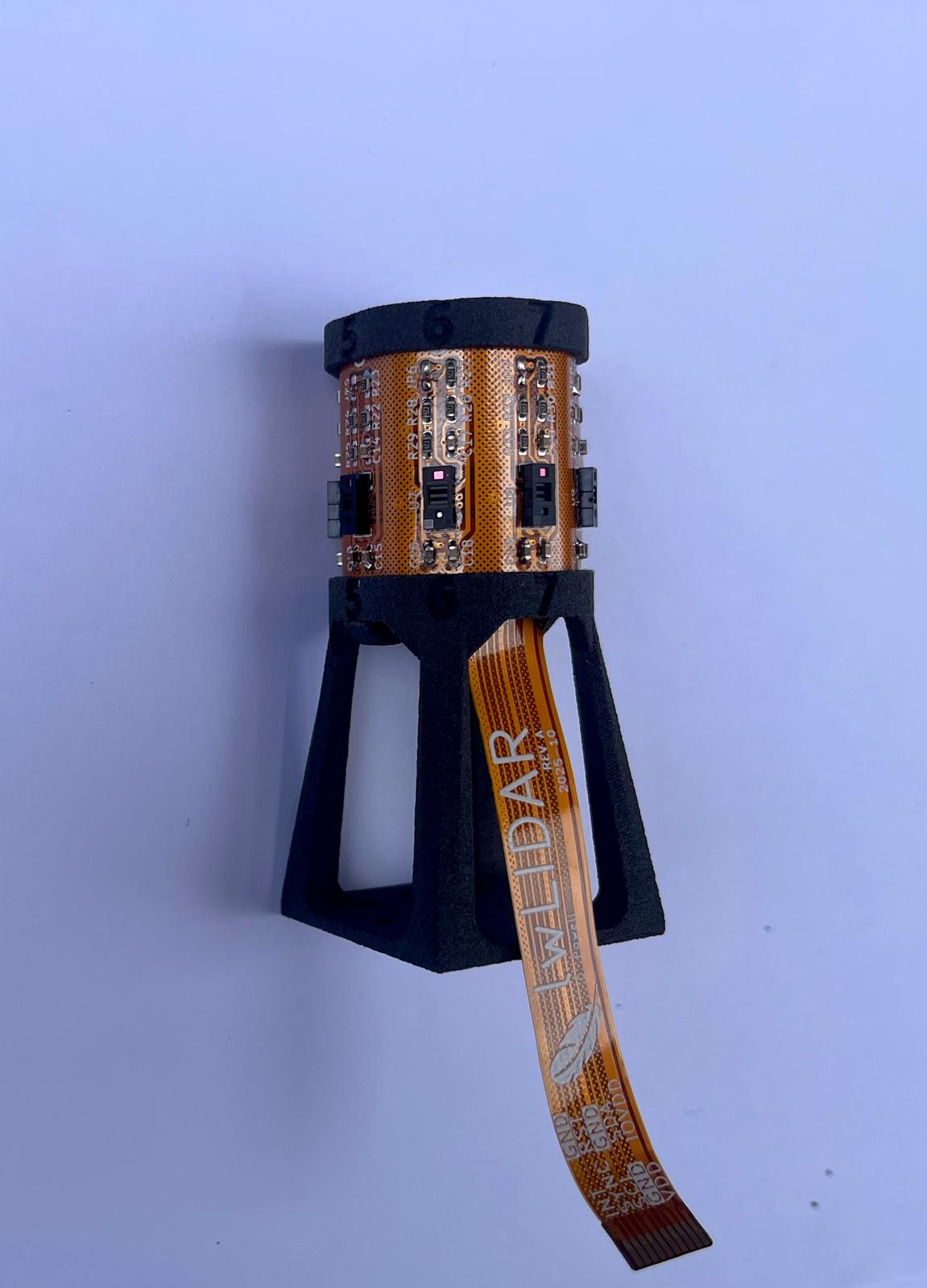
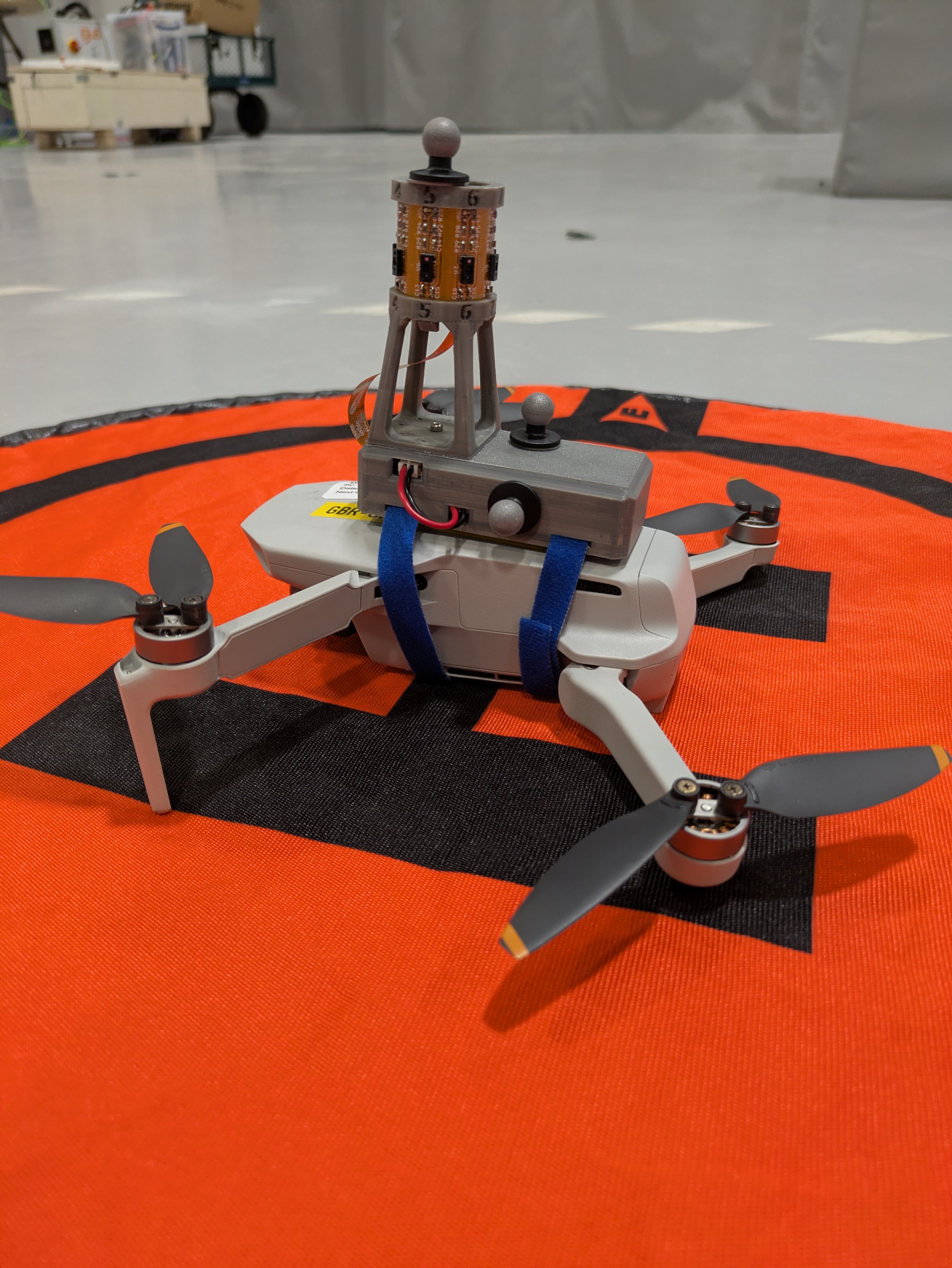
lwLIDAR is a research project aiming to design, implement and test a low-cost compact 3D LiDAR for use in constrained robotics research. It consists of an array of 8 VL53L8CX 8x8 matrix LiDAR sensors mounted to a flexible PCB.
This repository contains all required design files to construct and program a lwLIDAR sensor with an interface board to act as a sample implementation. Each subdirectory contains a more detailed README file.
|-------------------|-------------------------| | Framerate | 16 Hz | | Maximum distance | 4 m | | Resolution | 8 v x256 h | | FoV | 45° v x 360° h | | Size | 31x31x67 mm (with mast) | | Weight | 11g |
| Power consumption | 1.5W |
|---|
This project is licensed under the GNU AGPL license (see LICENSE.txt).
If you have improvements or want this repo to link to a usecase you made, please submit a pull request! If you have problems, please open an issue - I'm happy to improve this repository over time!
| Qty | Value | Footprint | References |
|---|---|---|---|
| 35 | 47k | Resistor_SMD:R_0603_1608Metric_Pad0.98x0.95mm_HandSolder | R10, R11, R12, R13, R14, R15, R16, R17, R18, R19, R20, R21, R22, R23, R24, R25 +19 |
| 16 | 100nF | Capacitor_SMD:C_0603_1608Metric_Pad1.08x0.95mm_HandSolder | C2, C3, C5, C6, C8, C9, C11, C12, C14, C15, C17, C18, C20, C21, C23, C24 |
| 8 | 4.7uF | Capacitor_SMD:C_0603_1608Metric_Pad1.08x0.95mm_HandSolder | C1, C4, C7, C10, C13, C16, C19, C22 |
| 8 | INT_JMP | Capacitor_SMD:C_0603_1608Metric_Pad1.08x0.95mm_HandSolder | JP1, JP2, JP3, JP4, JP5, JP6, JP7, JP8 |
| 8 | VL53L7CXV0GC/1 | VL53L8CX:IC17_LGA16_STM | U2, U3, U4, U5, U6, U7, U8, U9 |
| 2 | 10k | Resistor_SMD:R_0603_1608Metric_Pad0.98x0.95mm_HandSolder | R1, R2 |
| 1 | Conn_01x10_Pin | FPC_Connector:Molex 10 Pin Flex 52207-1060 | J1 |
| 1 | FXL6408UMX | IO expander:QFN40P260X180X55-16N | U1 |
| 1 | LOGO | LOGO | G*** |


doppelgrau/esp32-f9p-io-board
An IO-PCB (two motor-driver/H-bridge, CAN, RS232, ADS1115, relay, ethernet, ardusimple f9p compatible connector) with an ESP32 for 12V power, three 15V tolerant analog inputs, three 5V tolerant inputs.


perc-sw/phyduino_pico2
CAD files for the student workshop Phyduino Pico2 Arduino IDE compatible board.


Staacks/gbinterceptor
Capture or stream Game Boy gameplay footage via USB without modifying the Game Boy.
It measures 98.8 × 98.4 mm and has 2 copper layers, 0.12 mm thick.
80 parts, built around the VL53L7CXV0GC/1 and FXL6408UMX. The full list of its parts is on this page, with links to each part's symbol and footprint where PCBKit's library has them.
From the 0sleep/lwLIDAR repository on GitHub, at the commit this page was made from: the board is Flex/sensor_board/sensor_board.kicad_pcb and its schematic Flex/sensor_board/sensor_board.kicad_sch. PCBKit opens the board in the browser, with nothing to install.
Its repository publishes it under the AGPL-3.0 licence: you may reuse it on that licence's terms (keep the author's notice, and for a copyleft licence share your changes alike).