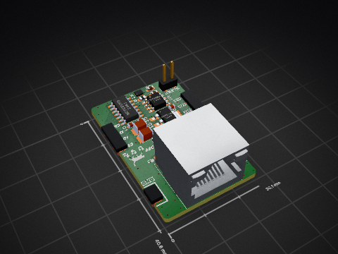
2 layers30 × 30 mm
ReCamera Gimbal
Seeed-Studio/OSHW-reCamera-Series
reCamera is a series of open-source AI cameras.
123 parts495Apache-2.0
Microchip TechnologyExtended
-40℃~+150℃ 3mA 4.5V~5.5V 55mA 8Mbps CAN Transceiver SOIC-8 CAN Transceivers ROHS
The MCP2558FD-H/SN is a CAN Transceiver made by Microchip Technology in a SOIC-8 package with 8 pins. -40℃~+150℃ 3mA 4.5V~5.5V 55mA 8Mbps CAN Transceiver SOIC-8 CAN Transceivers ROHS.
PCBKit's library has its KiCad symbol (EasyEDA_Cloud:MCP2558FD-H_SN, from EasyEDA) and its footprint (Package_SO:SOIC-8_3.9x4.9mm_P1.27mm, from KiCad's library), ready for a KiCad board. 4,371 are in stock at JLCPCB (part C623216). 12 open-source boards in 6 repositories on GitHub use it.
| Parameter | Conditions | As printed | Page |
|---|---|---|---|
| VDD VDD | max 7 V | 10 | |
| VIO VIO | max 7 V | 10 | |
| DC Voltage at TXD, RXD, S and VSS | Maximum VIO + 0.3V | min -0.3 V | 10 |
| DC Voltage at CANH, and CANL | min -58 · max 58 V | 10 | |
| Transient Voltage on CANH, and CANL | ISO/DIS-7637; Figure 2-5 | min -150 · max 100 V | 10 |
| Differential Bus Input Voltage VDIFF(I) | t = 60 days, continuous | min -5 · max 10 V | 10 |
| Differential Bus Input Voltage VDIFF(I) | 1000 pulses, t = 0.1 ms, VCANH = +18V | max 17 V | 10 |
| Dominant State Detection VDIFF(I) | 10000 pulses, t = 1 ms | max 9 V | 10 |
| Storage temperature | min -55 · max 150 °C | 10 | |
| Operating ambient temperature | min -40 · max 150 °C | 10 | |
| Virtual Junction Temperature TVJ | IEC60747-1 | min -40 · max 190 °C | 10 |
| Soldering temperature of leads | 10 seconds | max 300 °C | 10 |
| ESD protection on CANH and CANL pins | IEC 61000-4-2 | min -13 · max 13 kV | 10 |
| ESD protection on CANH and CANL pins | IEC 801; Human Body Model | min -8 · max 8 kV | 10 |
| ESD protection on all other pins | IEC 801; Human Body Model | min -4 · max 4 kV | 10 |
| ESD protection on all pins | IEC 801; Machine Model | min -400 · max 400 V | 10 |
| ESD protection on all pins | IEC 801; Charge Device Model | min -750 · max 750 V | 10 |
| Voltage Range VDD | VDD Pin | min 4.5 · max 5.5 V | 11 |
| Supply Current IDD | Recessive; VTXD = VDD | typ 2.5 · max 5 mA | 11 |
| Supply Current IDD | Dominant; VTXD = 0V | typ 55 · max 70 mA | 11 |
| Silent Current IDDS | MCP2558FD Includes IIO | typ 1 · max 3 mA | 11 |
| Maximum Supply Current IDDMAX | Fault condition: VTXD = VSS; VCANH = VCANL = -5V to +18V | typ 95 · max 140 mA | 11 |
| High Level of the POR Comparator for VDD VPORH | Note 1 | typ 3 · max 3.95 V | 11 |
| Low Level of the POR Comparator for VDD VPORL | Note 1 | min 1 · typ 2 · max 3.2 V | 11 |
| Hysteresis of POR Comparator for VDD VPORD | Note 1 | min 0.2 · typ 0.9 · max 2 V | 11 |
| High Level of the UV Comparator for VDD VUVH | min 4 · typ 4.25 · max 4.4 V | 11 | |
| Low Level of the UV Comparator for VDD VUVL | min 3.6 · typ 3.8 · max 4 V | 11 | |
| Hysteresis of UV comparator VUVD | Note 1 | typ 0.4 V | 11 |
| Digital Supply Voltage Range VIO | MCP2558FD | min 1.7 · max 5.5 V | 11 |
| Supply Current on VIO IIO | Recessive; VTXD = VIO | typ 7 · max 30 uA | 11 |
| Supply Current on VIO IIO | Dominant; VTXD = 0V | typ 200 · max 400 uA | 11 |
| High Level of the POR Comparator for VIO VPORH_VIO | MCP2558FD | min 0.8 · typ 1.2 · max 1.7 V | 11 |
| Low Level of the POR Comparator for VIO VPORL_VIO | MCP2558FD | min 0.7 · typ 1.1 · max 1.4 V | 11 |
| Hysteresis of POR Comparator for VIO VPORD_VIO | MCP2558FD | typ 0.2 V | 11 |
| CANH; CANL: Recessive Bus Output Voltage VO(R) | VTXD = VDD; No load; typical 0.5 VDD | min 2 · max 3 V | 11 |
| Recessive Output Current IO(R) | -24V < VCAN < +24V | min -5 · max 5 mA | 11 |
| CANH: Dominant Output Voltage VO(D) | TXD = 0; RL = 50 to 65 | min 2.75 · typ 3.5 · max 4.5 V | 11 |
| CANL: Dominant Output Voltage VO(D) | TXD = 0; RL = 50 to 65 | min 0.5 · typ 1.5 · max 2.25 V | 11 |
| Driver Symmetry (VCANH+VCANL)/VDD VSYM | 1 MHz square wave, Recessive and Dominant states, and transition (Note 1) | min 0.9 · typ 1 · max 1.1 V | 11 |
| Dominant: Differential Output Voltage VO(DIFF)(D) | VTXD = VSS; RL = 50 to 65; Figure 2-2, Figure 2-4; Note 1 | min 1.5 · typ 2 · max 3 V | 12 |
| Dominant: Differential Output Voltage VO(DIFF)(D) | VTXD = VSS; RL = 45 to 70; Figure 2-2, Figure 2-4, Section 3; Note 1 | min 1.4 · typ 2 · max 3 V | 12 |
| Dominant: Differential Output Voltage VO(DIFF)(D) | VTXD = VSS; RL = 40 to 75; Figure 2-2, Figure 2-4, Section 3 | min 1.3 · typ 2 · max 3 V | 12 |
| Dominant: Differential Output Voltage VO(DIFF)(D) | VTXD = VSS; RL = 2240; Figure 2-2, Figure 2-4, Section 3; Note 1 | min 1.5 · max 5 V | 12 |
| Recessive: Differential Output Voltage VO(DIFF)(R) | VTXD = VDD, no load; Figure 2-2, Figure 2-4 | min -500 · typ 0 · max 50 mV | 12 |
| CANH: Short-Circuit Output Current IO(SC) | VTXD = VSS; VCANH = -3V; CANL: floating | min -115 · typ -85 mA | 12 |
| CANL: Short Circuit Output Current IO(SC) | VTXD = VSS; VCANL = +18V; CANH: floating | typ 75 · max 115 mA | 12 |
| Recessive Differential Input Voltage VDIFF(R)(I) | -12V < V(CANH, CANL) < +12V; see Figure 2-6 (Note 3) | min -4 · max 0.5 V | 12 |
| Dominant Differential Input Voltage VDIFF(D)(I) | -12V < V(CANH, CANL) < +12V; see Figure 2-6 (Note 3) | min 0.9 · max 9 V | 12 |
| Differential Receiver Threshold VTH(DIFF) | -12V < V(CANH, CANL) < +12V; see Figure 2-6 (Note 3) | min 0.5 · typ 0.7 · max 0.9 V | 12 |
| Differential Input Hysteresis VHYS(DIFF) | See Figure 2-6, (Note 1) | min 30 · max 200 mV | 12 |
| Single Ended Input Resistance RCAN_H, RCAN_L | Note 1 | min 6 · max 50 k | 12 |
| Internal Resistance Matching mR=2*(RCANH-RCANL)/(RCANH+RCANL) mR | VCANH = VCANL (Note 1) | min -3 · typ 0 · max 3 % | 12 |
| Differential Input Resistance RDIFF | Note 1 | min 12 · typ 25 · max 100 k | 12 |
| Internal Capacitance CIN | 1 Mbps (Note 1) | typ 20 pF | 12 |
| Differential Internal Capacitance CDIFF | 1 Mbps (Note 1) | typ 10 pF | 12 |
| CANH, CANL: Input Leakage ILI | VDD = VTXD = VS = 0V; MCP2558FD, VIO = 0V; VCANH = VCANL = 5 V | min -5 · max 5 uA | 12 |
| Low-Level Input Voltage VIL | MCP2558FD; TXD, S; maximum 0.3VIO | min -0.3 V | 13 |
| High-Level Input Current IIH | TXD, S | min -1 · max 1 uA | 13 |
| TXD: Low-Level Input Current IIL(TXD) | min -270 · typ -150 · max -30 uA | 13 | |
| S: Low-Level Input Current IIL(S) | min -30 · max -1 uA | 13 | |
| Low-Level Output Voltage VOL | IOL = 4 mA; typical 8 mA | max 0.4 V | 13 |
| Shutdown Junction Temperature TJ(SD) | -12V < V(CANH, CANL) < +12V (Note 1) | min 165 · typ 175 · max 185 °C | 13 |
| Shutdown Temperature Hysteresis TJ(HYST) | -12V < V(CANH, CANL) < +12V (Note 1) | min 15 · max 30 °C | 13 |
| Bit Time tBIT | min 0.125 · max 69.44 us | 14 | |
| Nominal Bit Rate NBR | min 14.4 · max 8000 kbps | 14 | |
| Delay TXD Low to Bus Dominant tTXD-BUSON | Note 1 | typ 50 · max 85 ns | 14 |
| Delay TXD High to Bus Recessive tTXD-BUSOFF | Note 1 | typ 40 · max 85 ns | 14 |
| Delay Bus Dominant to RXD tBUSON-RXD | Note 1 | typ 70 · max 85 ns | 14 |
| Delay Bus Recessive to RXD tBUSOFF-RXD | Note 1 | typ 110 · max 145 ns | 14 |
| Propagation Delay TXD to RXD Worst Case of tLOOP(R) and tLOOP(F) Figure 2-9 tTXD - RXD | typ 90 · max 120 ns | 15 | |
| Propagation Delay TXD to RXD Worst Case of tLOOP(R) and tLOOP(F) Figure 2-9 tTXD - RXD | RL = 150, CL = 200 pF (Note 1) | typ 115 · max 150 ns | 15 |
| Propagation Delay, Rising Edge tLOOP(R) | typ 90 · max 120 ns | 15 | |
| Propagation Delay, Falling Edge tLOOP(F) | typ 80 · max 120 ns | 15 | |
| Recessive Bit Time on RXD – 1 Mbps, Loop Delay Symmetry (Note 2) tBIT(RXD), 1M | tBIT(TXD) = 1000 ns (Figure 2-9) | min 900 · typ 985 · max 1100 ns | 15 |
| Recessive Bit Time on RXD – 1 Mbps, Loop Delay Symmetry (Note 2) tBIT(RXD), 1M | tBIT(TXD) = 1000 ns (Figure 2-9), RL = 150, CL = 200 pF (Note 1) | min 800 · typ 960 · max 1255 ns | 15 |
| Recessive Bit Time on RXD – 2 Mbps, Loop Delay Symmetry tBIT(RXD), 2M | tBIT(TXD) = 500 ns (Figure 2-9) | min 450 · typ 490 · max 550 ns | 15 |
| Recessive Bit Time on RXD – 2 Mbps, Loop Delay Symmetry tBIT(RXD), 2M | tBIT(TXD) = 500 ns (Figure 2-9), RL = 150, CL = 200 pF (Note 1) | min 400 · typ 460 · max 550 ns | 15 |
| Recessive Bit Time on RXD – 5 Mbps, Loop Delay Symmetry tBIT(RXD), 5M | tBIT(TXD) = 200 ns (Figure 2-9) | min 160 · typ 190 · max 220 ns | 15 |
| Recessive Bit Time on RXD – 8 Mbps, Loop Delay Symmetry (Note 2) tBIT(RXD), 8M | tBIT(TXD) = 120 ns (Figure 2-9) (Note 1) | min 85 · typ 100 · max 135 ns | 15 |
| Delay Silent to Normal Mode tWAKE | Negative edge on S | typ 7 · max 30 us | 15 |
| Permanent Dominant Detect Time tPDT | TXD = 0V | min 0.8 · typ 1.9 · max 5 ms | 15 |
| Permanent Dominant Timer Reset tPDTR | The shortest recessive pulse on TXD or CAN bus to reset Permanent Dominant Timer | typ 5 ns | 15 |
| Transmitted Bit Time on Bus – 1 Mbps (Note 2) tBIT(BUS), 1M | tBIT(TXD) = 1000 ns (Figure 2-9) | min 870 · typ 1000 · max 1060 ns | 15 |
| Transmitted Bit Time on Bus – 1 Mbps (Note 2) tBIT(BUS), 1M | tBIT(TXD) = 1000 ns (Figure 2-9), RL = 150, CL = 200 pF (Note 1) | min 870 · typ 1000 · max 1060 ns | 15 |
| Transmitted Bit Time on Bus – 2 Mbp tBIT(BUS), 2M | tBIT(TXD) = 500 ns (Figure 2-9) | min 435 · typ 515 · max 530 ns | 15 |
| Transmitted Bit Time on Bus – 2 Mbp tBIT(BUS), 2M | tBIT(TXD) = 500 ns (Figure 2-9) RL = 150, CL = 200 pF (Note 1) | min 435 · typ 480 · max 550 ns | 15 |
| Transmitted Bit Time on Bus – 5 Mbps tBIT(BUS), 5M | tBIT(TXD) = 200 ns (Figure 2-9) (Note 1) | min 155 · typ 200 · max 210 ns | 16 |
| Transmitted Bit Time on Bus - 8Mbps (Note 2) tBIT(BUS), 8M | tBIT(TXD) = 120 ns (Figure 2-9) (Note 1) | min 100 · typ 125 · max 140 ns | 16 |
| Receiver Timing Symmetry – 1 Mbps (Note 2) tDIFF(REC), 1M = tBIT(RXD) - tBIT(BUS) | tBIT(TXD) = 1000 ns (Figure 2-9) | min -65 · typ 0 · max 40 ns | 16 |
| Receiver Timing Symmetry – 1 Mbps (Note 2) tDIFF(REC), 1M = tBIT(RXD) - tBIT(BUS) | tBIT(TXD) = 1000 ns (Figure 2-9), RL = 150, CL = 200 pF (Note 1) | min -130 · typ 0 · max 80 ns | 16 |
| Receiver Timing Symmetry – 2 Mbps tDIFF(REC), 2M | tBIT(TXD) = 500 ns (Figure 2-9) | min -65 · typ 0 · max 40 ns | 16 |
| Receiver Timing Symmetry – 2 Mbps tDIFF(REC), 2M | tBIT(TXD) = 500 ns (Figure 2-9), RL = 150, CL = 200 pF (Note 1) | min -70 · typ 0 · max 40 ns | 16 |
| Receiver Timing Symmetry – 5 Mbps tDIFF(REC), 5M | tBIT(TXD) = 200 ns (Figure 2-9) (Note 1) | min -45 · typ 0 · max 15 ns | 16 |
| Receiver Timing Symmetry – 8 Mbps (Note 2) tDIFF(REC), 8M | tBIT(TXD) = 120 ns (Figure 2-9) (Note 1) | min -45 · typ 0 · max 10 ns | 16 |
| Specified Temperature Range TA | min -40 · max 150 C | 19 | |
| Operating Temperature Range TA | min -40 · max 150 C | 19 | |
| Storage Temperature Range TA | min -65 · max 155 C | 19 | |
| Thermal Resistance, 8LD SOIC JA | 8LD SOIC | typ 149.5 C/W | 19 |
Seeed-Studio/OSHW-reCamera-Series
reCamera is a series of open-source AI cameras.

Maritime-Hacking-Village/Badge-2025
Public repository for the official MHV 2025 badge.

RealtimeRoboticsGroup/electrical
This project is open-source hardware and is licensed under the Solderpad Hardware License v2.1 (the "License"), which is a permissive license based on the Apache License, Version 2.0.

frc971/electrical
This repo contains the electrical files for the 971 FRC team. The files include PCBs and the electrical system diagrams. The PCBs are created using KiCad.

frc971/electrical
This repo contains the electrical files for the 971 FRC team. The files include PCBs and the electrical system diagrams. The PCBs are created using KiCad.

frc971/electrical
This repo contains the electrical files for the 971 FRC team. The files include PCBs and the electrical system diagrams. The PCBs are created using KiCad.

RealtimeRoboticsGroup/electrical
This project is open-source hardware and is licensed under the Solderpad Hardware License v2.1 (the "License"), which is a permissive license based on the Apache License, Version 2.0.

Yes. The symbol is EasyEDA_Cloud:MCP2558FD-H_SN and the footprint Package_SO:SOIC-8_3.9x4.9mm_P1.27mm, both drawn on this page. PCBKit places them on a board for you when you design with it.
SOIC-8, with 8 pins. Its footprint is drawn on this page.
Microchip Technology publishes it: the Datasheet link on this page opens it.
JLCPCB lists it as part C623216, with 4,371 in stock; the sellers' links on this page open their listings.
Parts like it in the library: the TJA1051T/3/1J by NXP Semiconductors, the SN65HVD230D by Texas Instruments, the TJA1042T/1J by NXP Semiconductors and the CA-IF1051S by Chipanalog. Check their datasheets: a part that fits the footprint may still differ in its ratings.
12 boards in 6 repositories on GitHub; the most starred are listed on this page, with their KiCad files.