4 layers183 × 165 mm

 ZeniteSolar/MCC221
Follow the steps below, if any value differs from the expected, abort the test. Power off and on after each step. Always limit the power source to 18V at 100mA. Use this link to find components on the board.
MCC22 is an open-source printed circuit board by ZeniteSolar, from the ZeniteSolar/MCC22 repository on GitHub. It is a 4-layer board of 71.8 × 109.5 mm with 245 parts on 129 nets, routed with 1,617 tracks and 5,345 vias.
It is built around the 1EDI60N12AF, AMS1117-3.3 and ESD351DPYR, with the BSC093N15NS5, SMF100A and SMF64A among its other parts. Its parts include 55 resistors, 48 capacitors, 26 diodes, 6 ICs and 3 connectors. It belongs with the STM32 boards of this library.


MPPT Battery charger
| Input Voltage | 0 ~ 30 V |
|---|---|
| Output Voltage | 21 ~ 60V |
| Output Power | 300 W |
| Efficiency | > 90% |
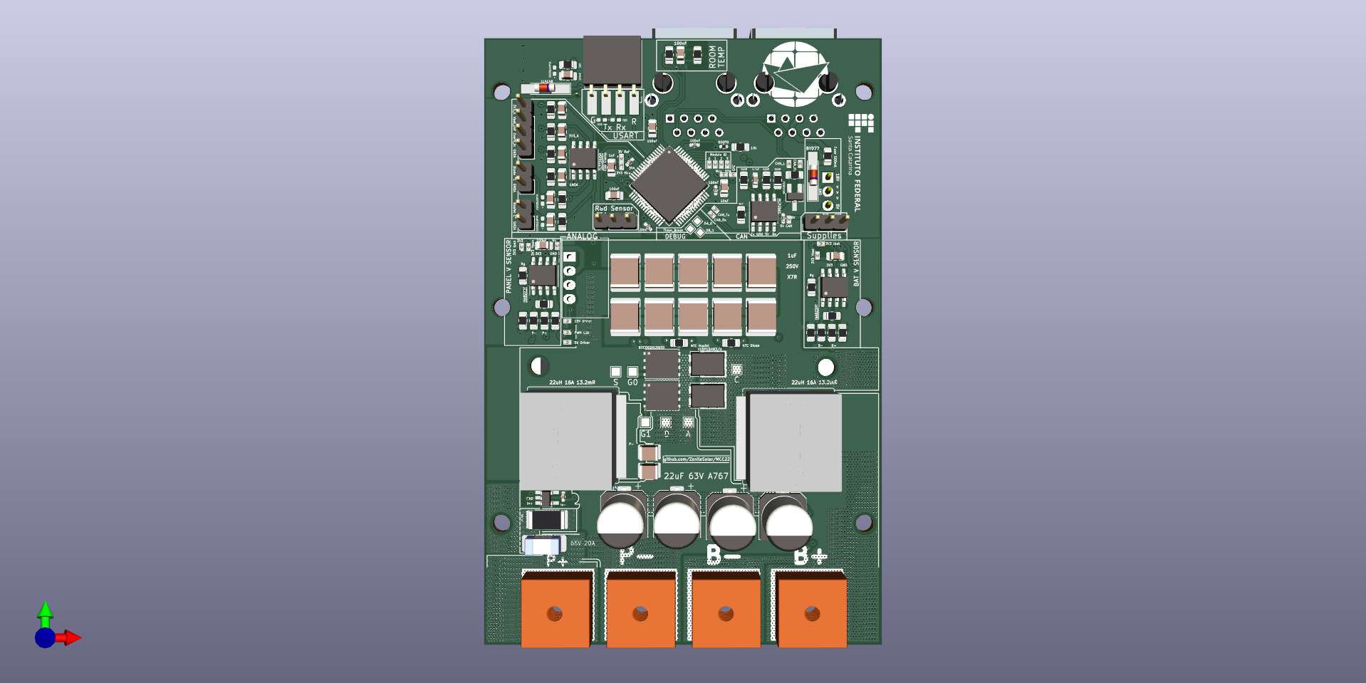
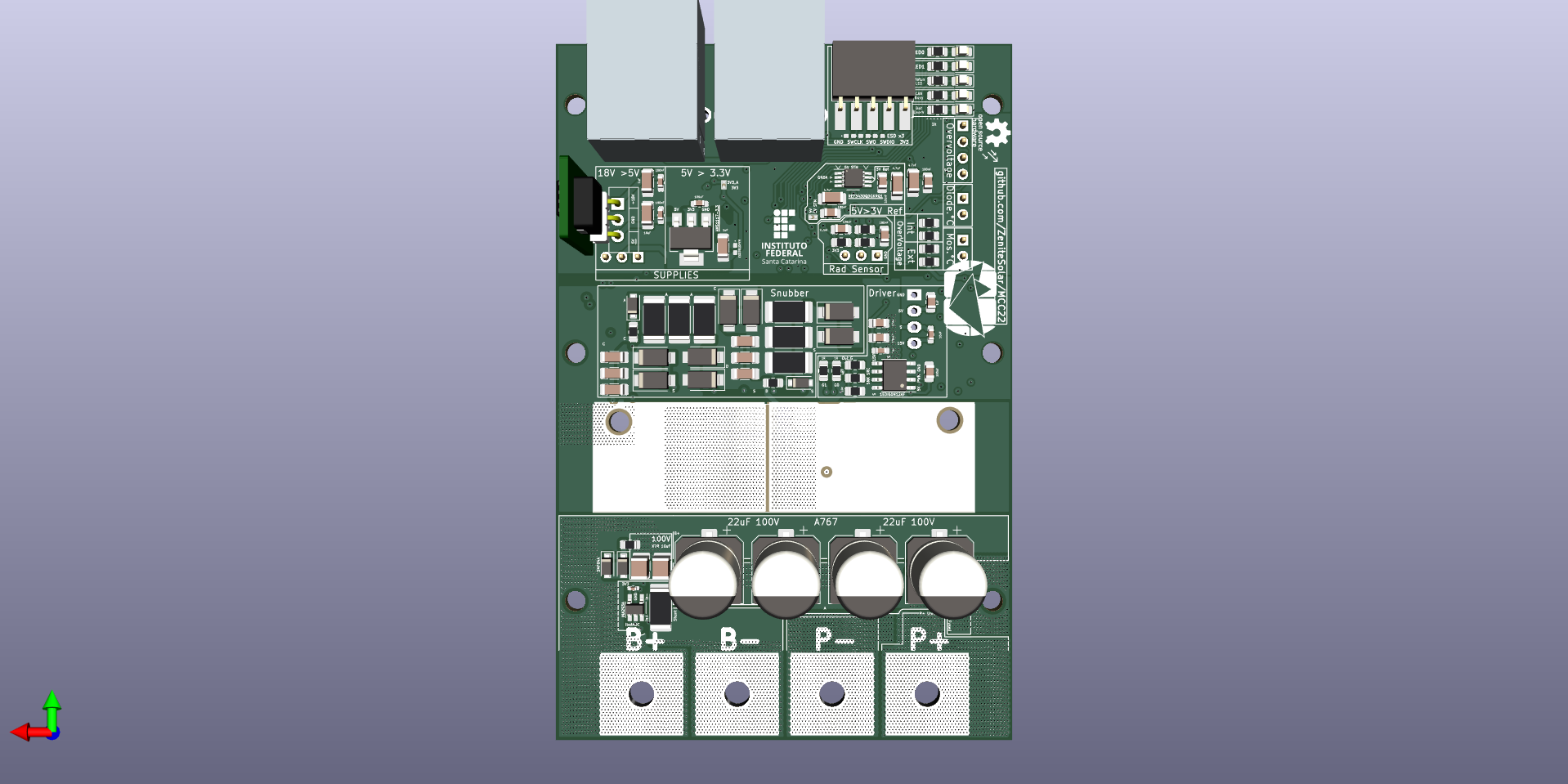
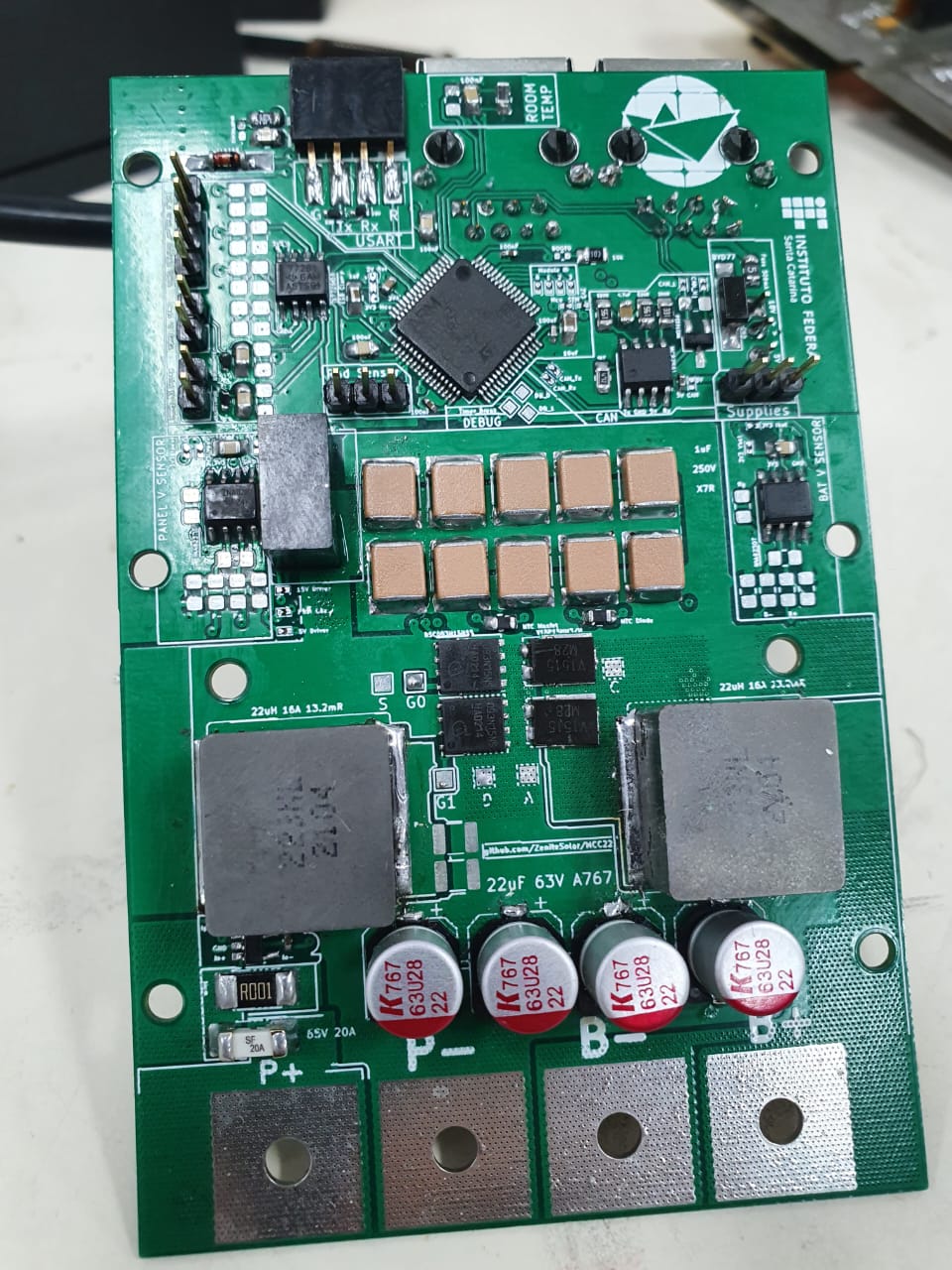
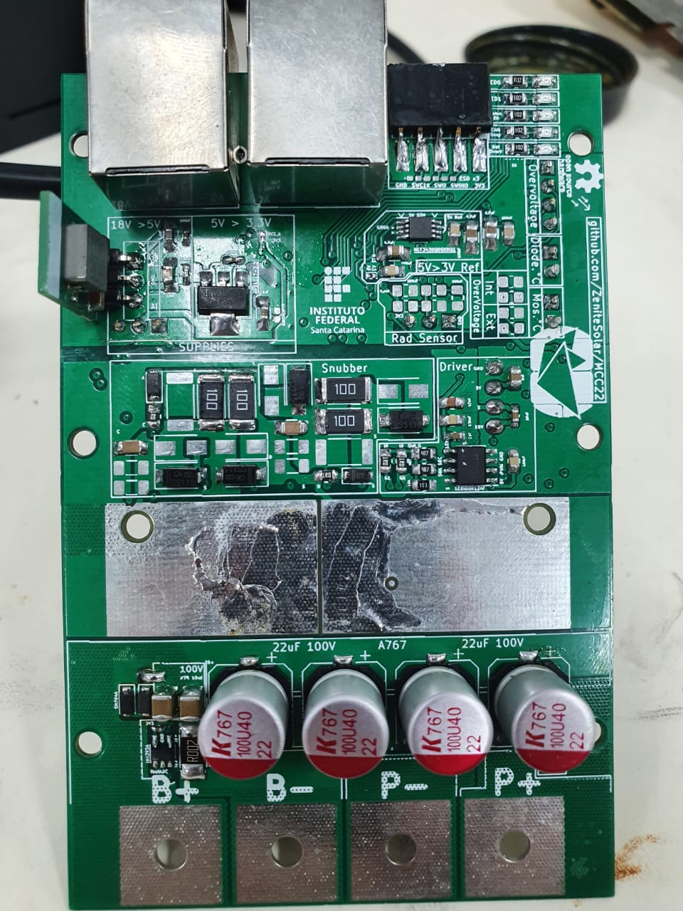
Follow the steps below, if any value differs from the expected, abort the test. Power off and on after each step. Always limit the power source to 18V at 100mA. Use this link to find components on the board.
WRTE:SYST:PING? to verify if UART is functioning, the response should be PONG.READ:MEAS:ALLM?. After activating this flag, the board will continuously send the measurements it takes.WRTE:CTRL:ALGO:FIXD:0000.0000 to deactivate the PWM.WRTE:CTRL:ALGO:FIXD:0000.6000 to fix the PWM at 60%. Attach the oscilloscope's GND to test point S (TP404) Other channels should have their GND disconnected! and channel 1 to test point G0 (TP401). There should appear a square signal with a 60% duty cycle, same for G1 (TP402).WRTE:CTRL:ALGO:FIXD:0000.6000, connect a voltage source at P+ and P- with zero voltage and current at 1A, increase the voltage until the source limits and the Ipan value on UART should follow the source current.Note: If any of the conditions are not met, there might be a potential issue with the board.
All tests are in this separated document.
| Qty | Value | Footprint | References |
|---|---|---|---|
| 24 | ? | Resistor_SMD:R_0805_2012Metric_Pad1.20x1.40mm_HandSolder | R301, R302, R303, R304, R305, R306, R307, R308, R309, R310, R311, R312, R313, R314, R315, R316 +8 |
| 15 | 50V 100nF 0805 | Capacitor_SMD:C_0805_2012Metric_Pad1.18x1.45mm_HandSolder | C202, C203, C205, C206, C207, C301, C302, C303, C304, C307, C308, C314, C315, C503, C505 |
| 10 | 250V 1uF X7R ±10% 20mR 2220 | Capacitor_SMD:C_2220_5650Metric | Cc401, Cc402, Cc403, Cc404, Cc405, Cc406, Cc407, Cc408, Cc409, Cc410 |
| 9 | ESD351DPYR | Diode_SMD:D_0402_1005Metric_Pad0.77x0.64mm_HandSolder | D103, D104, D105, D106, D107, D108, D301, D302, D601 |
| 8 | C2848681 150V 1A Schottky | Diode_SMD:D_SMA | D401, D402, D403, D404, D408, D409, D410, D411 |
| 6 | , , , , , | ||
| 6 | 2W 200V 10R ±5% 2512 | Resistor_SMD:R_2512_6332Metric_Pad1.40x3.35mm_HandSolder | R402, R403, R404, R409, R410, R411 |
| 6 | 50V 100nF X7R ±10% 0402 | Capacitor_SMD:C_0402_1005Metric_Pad0.74x0.62mm_HandSolder | C208, C209, C210, C305, C306, C701 |
| 6 | NC | Capacitor_SMD:C_1206_3216Metric_Pad1.33x1.80mm_HandSolder | C402, C403, C404, C406, C407, C408 |
| 5 | 1kR 0805 | Resistor_SMD:R_0805_2012Metric_Pad1.20x1.40mm_HandSolder | R204, R205, R206, R207, R208 |
| 4 | 100V 22uF A767 ±20% 38mR EB | Capacitor_SMD:CP_Elec_10x12.5 | Co403, Co404, Co405, Co406 |
| 4 | 63V 22uF A767 ±20% EB | Capacitor_SMD:CP_Elec_8x10 | Ci403, Ci404, Ci405, Ci406 |
| 4 | ? | Capacitor_SMD:C_0805_2012Metric_Pad1.18x1.45mm_HandSolder | C309, C310, C311, C312 |
| 3 | 0R | Resistor_SMD:R_0805_2012Metric_Pad1.20x1.40mm_HandSolder | R407, R408, R412 |
| 3 | 10kR 0805 | Resistor_SMD:R_0805_2012Metric_Pad1.20x1.40mm_HandSolder | R202, R203, R401 |
| 3 | 50V 100nF X7R ±10% 0402 | Capacitor_SMD:C_0603_1608Metric_Pad1.08x0.95mm_HandSolder | C602, C604, C605 |
| 3 | 50V 4.7uF X7R ±10% 1206 | Capacitor_SMD:C_1206_3216Metric_Pad1.33x1.80mm_HandSolder | C201, C204, C313 |
| 3 | GNDA | Zenite:NetTie-2_SMD_Pad0.3mm | NT201, NT301, NT302 |
| 3 | NC | Resistor_SMD:R_0805_2012Metric_Pad1.20x1.40mm_HandSolder | R322, R323, R705 |
| 3 | NTC 10k 1SDNT2012X103F3950FTF | Resistor_SMD:R_0805_2012Metric_Pad1.20x1.40mm_HandSolder | TH301, TH302, TH303 |
| 3 | NetTie_2 | Zenite:NetTie-2_SMD_Pad0.3mm | NT101, NT102, NT104 |
| 2 | 100V 10uF X7R ±10% 3mR 1210 | Capacitor_SMD:C_1210_3225Metric | Co401, Co402 |
| 2 | 1R 0805 | Resistor_SMD:R_0805_2012Metric_Pad1.20x1.40mm_HandSolder | R405, R406 |
| 2 | 22uH 16A 13.2mOhms Shilded, ( ~3W core + copper losses) | Zenite:L_Pulse_PM227 | L401, Li401 |
| 2 | 25V 10uF X5R ±10% 0805 | Capacitor_SMD:C_0805_2012Metric_Pad1.18x1.45mm_HandSolder | C212, C502 |
| 2 | 4.7R 0805 | Resistor_SMD:R_0805_2012Metric_Pad1.20x1.40mm_HandSolder | R501, R502 |
| 2 | 50V 1uF X5R ±10% 0603 | Capacitor_SMD:C_0603_1608Metric_Pad1.08x0.95mm_HandSolder | C501, C506 |
| 2 | 50V 1uF X5R ±10% 0603 | Capacitor_SMD:C_1206_3216Metric_Pad1.33x1.80mm_HandSolder | C601, C606 |
| 2 | 520R 0805 | Resistor_SMD:R_0805_2012Metric_Pad1.20x1.40mm_HandSolder | R703, R704 |
| 2 | BSC093N15NS5 | Zenite:TDSON-8-3 | Q401, Q402 |
| 2 | Enable_Driver | Zenite:SolderJumper-2_P0.5mm_Open_TrianglePad0.8x0.5mm | JP104, JP501 |
| 2 | Heatsink | MountingHole:MountingHole_3.2mm_M3 | H401, H402 |
| 2 | INA293A4 | Package_TO_SOT_SMD:SOT-23-5_HandSoldering | U303, U304 |
| 2 | INA823DT | Package_SO:SOIC-8_3.9x4.9mm_P1.27mm | U301, U302 |
| 2 | Logo_Open_Hardware_Big | Zenite:symbol_logoZenite | LOGO104, LOGO104 |
| 2 | Logo_Open_Hardware_Small | Zenite:synbol_logoifsc | LOGO102, LOGO102 |
| 2 | NC | Capacitor_SMD:C_1210_3225Metric | Ci401, Ci402 |
| 2 | RJ45_Shielded | Zenite:RJ45_YH59_01 | J801, J802 |
| 2 | SMF100A | Diode_SMD:D_SOD-123F | D405, D412 |
| 2 | SMF64A | Diode_SMD:D_SOD-123F | D413, D414 |
| 2 | V15P15HM3/H | Package_TO_SOT_SMD:TO-277A | D406, D407 |
| 1 | 1.0mR 1% 5W 50ppm | Resistor_SMD:R_2512_6332Metric_Pad1.40x3.35mm_HandSolder | R101 |
| 1 | 1.5mR 1% 5W 50ppm | Resistor_SMD:R_2512_6332Metric_Pad1.40x3.35mm_HandSolder | R102 |
| 1 | 1EDI60N12AF | Package_SO:SOIC-8_3.9x4.9mm_P1.27mm | U501 |
| 1 | 25V 10uF X5R ±10% 0805 | Capacitor_SMD:C_1206_3216Metric_Pad1.33x1.80mm_HandSolder | C603 |
| 1 | 300R 0805 | Resistor_SMD:R_0805_2012Metric_Pad1.20x1.40mm_HandSolder | R702 |
| 1 | 3V3S | Zenite:NetTie-2_SMD_Pad0.3mm | NT203 |
| 1 | 4k7 0805 | Resistor_SMD:R_0805_2012Metric_Pad1.20x1.40mm_HandSolder | R701 |
| 1 | 500mA SMD0805B050TF | Fuse:Fuse_0805_2012Metric_Pad1.15x1.40mm_HandSolder | F102 |
| 1 | 50V 10nF 0805 | Capacitor_SMD:C_0805_2012Metric_Pad1.18x1.45mm_HandSolder | C504 |
| 1 | 50V 10nF X7R ±10% 0402 | Capacitor_SMD:C_0402_1005Metric_Pad0.74x0.62mm_HandSolder | C211 |
| 1 | 50V 1uF X7R ±10% 0805 | Capacitor_SMD:C_0805_2012Metric_Pad1.18x1.45mm_HandSolder | C213 |
| 1 | 50V 4.7nF X7R ±5% 0603 | Capacitor_SMD:C_0603_1608Metric_Pad1.08x0.95mm_HandSolder | C702 |
| 1 | 65V 20A 3mOhms Fuse | Zenite:S6125-F | F101 |
| 1 | A | TestPoint:TestPoint_Pad_1.5x1.5mm | TP406 |
| 1 | AMS1117-3.3 | Package_TO_SOT_SMD:SOT-223-3_TabPin2 | U602 |
| 1 | Analog_Ref | Zenite:SolderJumper-3_P0.5mm_Open_TrianglePad0.8x0.5mm | JP203 |
| 1 | B+ | Zenite:MountingHole_13mmx13mm_Rectangular | H104 |
| 1 | B- | Zenite:MountingHole_13mmx13mm_Rectangular | H103 |
| 1 | BOOT0 | Resistor_SMD:R_0402_1005Metric | R201 |
| 1 | BYD77 | Diode_SMD:D_MiniMELF_Handsoldering | D102 |
| 1 | Bat_OverV_Out | LED_SMD:LED_0805_2012Metric_Pad1.15x1.40mm_HandSolder | D205 |
| 1 | C | TestPoint:TestPoint_Pad_1.5x1.5mm | TP405 |
| 1 | CAN_BUSY | LED_SMD:LED_0805_2012Metric_Pad1.15x1.40mm_HandSolder | D201 |
| 1 | CAN_H | Zenite:SolderJumper-2_P0.5mm_Open_TrianglePad0.8x0.5mm | JP109 |
| 1 | CAN_L | Zenite:SolderJumper-2_P0.5mm_Open_TrianglePad0.8x0.5mm | JP110 |
| 1 | CAN_RX | Zenite:SolderJumper-2_P0.5mm_Open_TrianglePad0.8x0.5mm | JP107 |
| 1 | CAN_TX | Zenite:SolderJumper-2_P0.5mm_Open_TrianglePad0.8x0.5mm | JP108 |
| 1 | D | TestPoint:TestPoint_Pad_1.5x1.5mm | TP403 |
| 1 | DB_0 | Zenite:TestPoint_Pad_1.0x1.0mm_small | TP201 |
| 1 | DB_1 | Zenite:TestPoint_Pad_1.0x1.0mm_small | TP202 |
| 1 | Diode_temp | Connector_PinHeader_2.54mm:PinHeader_1x02_P2.54mm_Vertical | J304 |
| 1 | Disabel_Ipanel | Zenite:SolderJumper-2_P0.5mm_Open_TrianglePad0.8x0.5mm | JP303 |
| 1 | Disable_Ibat | Zenite:SolderJumper-2_P0.5mm_Open_TrianglePad0.8x0.5mm | JP304 |
| 1 | Disable_Vbat | Zenite:SolderJumper-2_P0.5mm_Open_TrianglePad0.8x0.5mm | JP302 |
| 1 | Disable_Vpanel | Zenite:SolderJumper-2_P0.5mm_Open_TrianglePad0.8x0.5mm | JP301 |
| 1 | Enable Stm32 Supply | Zenite:SolderJumper-2_P0.5mm_Open_TrianglePad0.8x0.5mm | JP201 |
| 1 | Enable_Analog | Zenite:SolderJumper-2_P0.5mm_Open_TrianglePad0.8x0.5mm | JP102 |
| 1 | Enable_CAN | Zenite:SolderJumper-2_P0.5mm_Open_TrianglePad0.8x0.5mm | JP105 |
| 1 | Enable_Driver_5V | Zenite:SolderJumper-2_P0.5mm_Open_TrianglePad0.8x0.5mm | JP502 |
The 210 most common of 245 parts.
It measures 71.8 × 109.5 mm and has 4 copper layers, 1.6 mm thick.
245 parts, built around the 1EDI60N12AF, AMS1117-3.3, ESD351DPYR and BSC093N15NS5. The full list of its parts is on this page, with links to each part's symbol and footprint where PCBKit's library has them.
From the ZeniteSolar/MCC22 repository on GitHub, at the commit this page was made from: the board is hardware/main/main.kicad_pcb and its schematic hardware/main/Analog.kicad_sch. PCBKit opens the board in the browser, with nothing to install.
Its repository states no licence, so its author keeps all rights: ask ZeniteSolar before reusing the design.


joaomariolago/ifsc-pi3-eletronic-load
Simple eletronic load with WiFi integration and preprogramed operation curves


MatthiasGeorgImhof/STMF405_Flight_Controller
A flight controller inspired by Speedybee F405 v3 but with CAN and flash memory instead of flash card.

MatthiasGeorgImhof/STMF765_Flight_Controller
A flight controller inspired by Speedybee F405 v3 but with CAN using F7 MCU. Use flash memory instead of flash card.

holison-001/MVP-PPG
기존 PPG와 전선 6개로 연결하는 전이중 RS-422 ↔ 3.3V UART 변환 보드다. 같은 작업 폴더에 별도 KiCad 프로젝트로 작성했다. 외부 9V를 PPG와 공유하고, 사용자 지정 LD1117-3.3V로 이 보드의 통신부와 UART 포트용 3.3V를 만든다. MCU는 추가하지 않는다.