2 layers45.3 × 75.9 mm

 ZBZFirst/KiCad-Projects1
Custom ESP32 BLE HID controller + matching PCB design.
Attachment2 is an open-source printed circuit board by ZBZFirst, from the ZBZFirst/KiCad-Projects repository on GitHub. It is a 2-layer board of 52.8 × 49 mm with 6 parts on 22 nets, routed with 94 tracks and 0 vias.
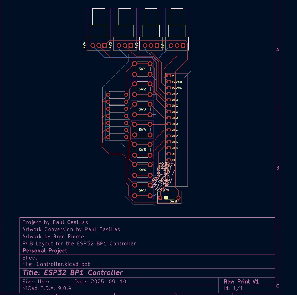
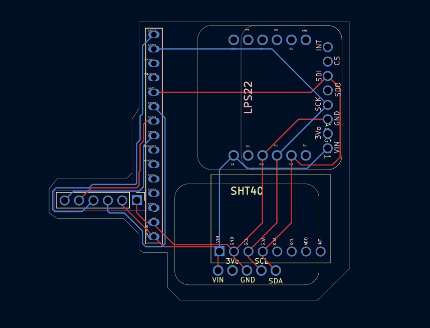
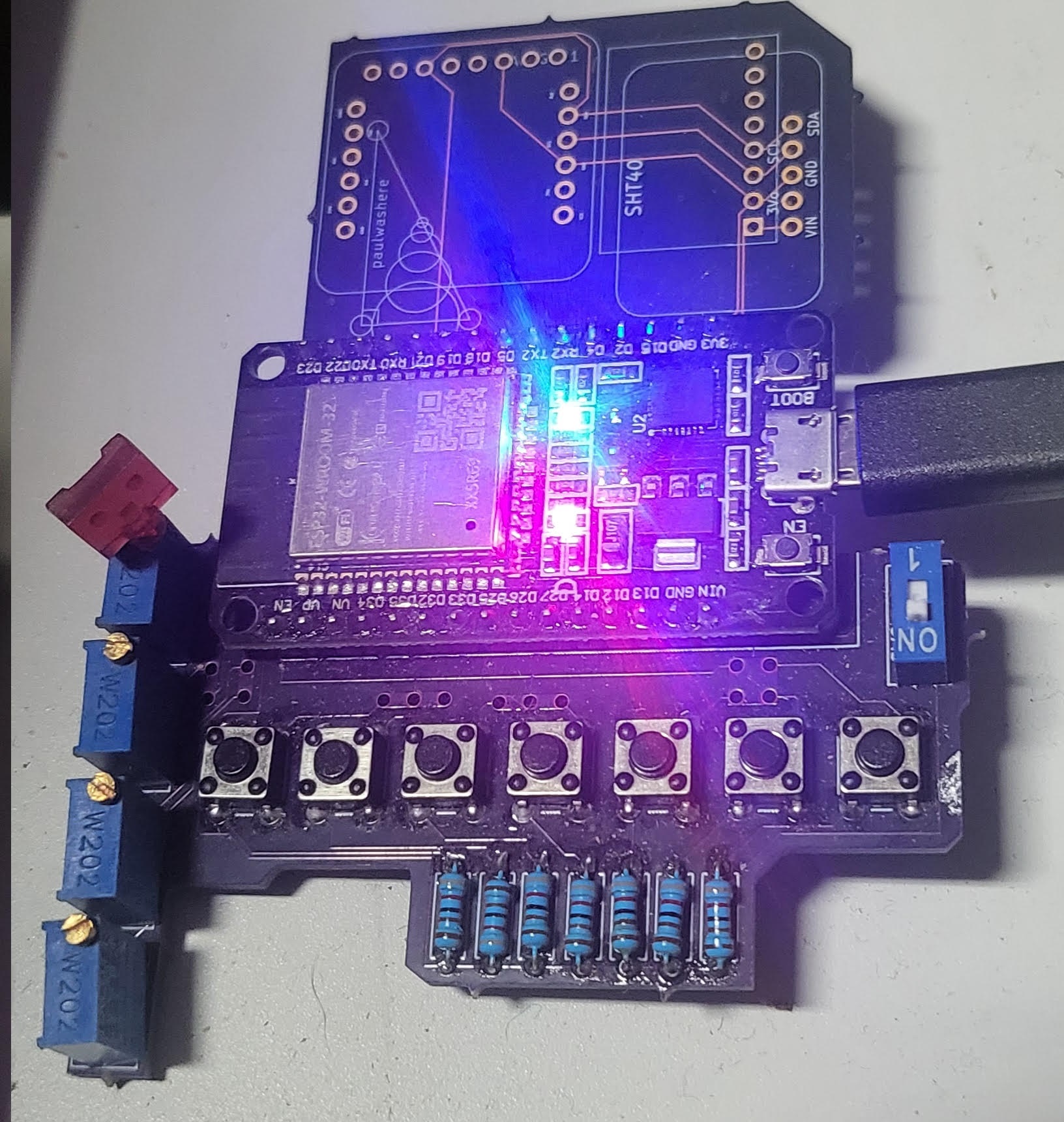
Custom ESP32 BLE HID controller + matching PCB design.
This project combines:
Designed as a personal hardware controller that behaves like a wireless keyboard/mouse macro pad.
ESP32-based custom PCB with:
KiCad layout included in repository.
File:
hardware/Controller.kicad_pcbThis board is designed specifically to run the included firmware.
The controller has 3 operating groups.
Button 6 cycles groups.
Button 7 forces disconnect (reboot).
| Button | Action |
|---|---|
| B1 | Ctrl + C |
| B2 | Ctrl + V |
| B3 | Ctrl + X |
| B4 | Ctrl + Z |
| B5 | 8-second mouse movement run |
LED: solid ON when connected
| Button | Action |
|---|---|
| B1 | Windows search → cmd → ssh CB37 |
| B2 | Launch Edge |
| B3 | Launch Super |
| B4 | Launch Arduino |
| B5 | Launch Bluetooth |
LED: 2 blink pattern
Toggle behaviors:
| Button | Mode |
|---|---|
| B1 | Auto left click |
| B2 | Auto right click |
| B3 | Auto middle click |
| B4 | Spam key “E” |
| B5 | Spam key “F” |
Press the same button again to stop.
LED: 3 blink pattern
Blink sequence repeats every 2 seconds.
Open:
firmware/PaulsESP32.inoCompile and upload to the board.
Designed primarily for Windows but functions as a generic BLE HID device.
firmware/
  PaulsESP32.ino

hardware/
  Controller.kicad_pcb
schematics/PCB + firmware design: Paul Casillas
Artwork: Bree Pierce
Personal project.
MIT — free to modify and build.
file is in
AutoClicker/AutoClickerbyController.ino
| Qty | Value | Footprint | References |
|---|---|---|---|
| 1 | 4 Pin Connector | UserDefined:MPU6050HiLetGO | MPU1 |
| 1 | ESP 32 RS | UserDefined:ESP32-DEVKITV1-Paul-Half2 | ESP32RightSide1 |
| 1 | SPISDCard | Connector_PinHeader_2.54mm:PinHeader_1x06_P2.54mm_Vertical | SDCardBoard1 |
| 1 | ~ | UserDefined:LPS22 | AdaLPS1 |
| 1 | ~ | UserDefined:Adafruit GPS PA1010D | AdaGPS1 |
| 1 | ~ | UserDefined:SHTBoard | AdaSHT1 |


byrantech/laptop
anyon_e, a highly integrated, high end, open source laptop. Attempt the impossible.


Jcparkyn/dpoint
Open-source digital stylus using camera tracking and inertial measurements

VoronDesign/Voron-Hardware
Cool Hardware designed by the Voron Design group

hoglet67/RGBtoHDMI
Bare-metal Raspberry Pi project that provides pixel-perfect sampling of Retro Computer RGB/YUV video and conversion to HDMI

hackclub/OnBoard
💡 Join 1,000 teenagers and make your first PCB with a $100 grant!

Luos-io/luos_engine
Open-source and real-time orchestrator for cyber-physical-systems, to easily design, test and deploy embedded applications and digital twins.

It measures 52.8 × 49 mm and has 2 copper layers, 1.6 mm thick.
6 parts. The full list of its parts is on this page, with links to each part's symbol and footprint where PCBKit's library has them.
From the ZBZFirst/KiCad-Projects repository on GitHub, at the commit this page was made from: the board is Attachment2/Attachment2.kicad_pcb and its schematic Attachment2/Attachment2.kicad_sch. PCBKit opens the board in the browser, with nothing to install.
Its repository states no licence, so its author keeps all rights: ask ZBZFirst before reusing the design.