
4 layers30.5 × 30.5 mm
Merlyn435
YeetTheAnson/Merlyn435-Flight-Stack
Successor to the Merlyn411 25mm flight controller. The flight stack includes a 3in1 20mm flight controller and a 20mm ESC.
106 parts6

STM32F411 Based AIO Flight Controller. Superseded by [Merlyn435](https://github.com/YeetTheAnson/Merlyn435-Flight-Stack/)
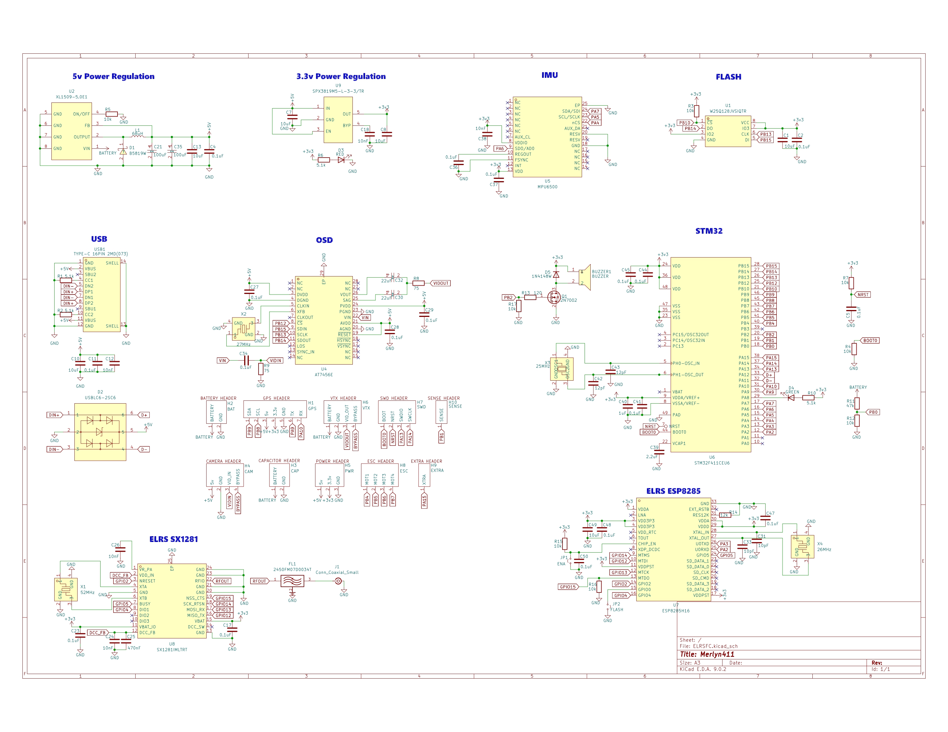
ELRSFC is an open-source printed circuit board by YeetTheAnson, from the YeetTheAnson/Merlyn411-FlightController repository on GitHub. It is a 2-layer board of 33.3 × 33.3 mm with 98 parts on 125 nets, routed with 1,022 tracks and 206 vias.
It is built around the AT7456E, STM32F411CEU6 and ESP8285H16, with the SX1281IMLTRT, 2450FM07D0034T and W25Q128JVSIQ TR among its other parts. Its parts include 40 capacitors, 17 resistors, 8 ICs, 5 diodes and 4 crystals. It belongs with the robots and motor control boards and the ESP8266 and STM32 boards of this library.


[!TIP] The Merlyn411 is outdated! Check out the Merlyn435 for a more powerful and modern flight controller + ESC.
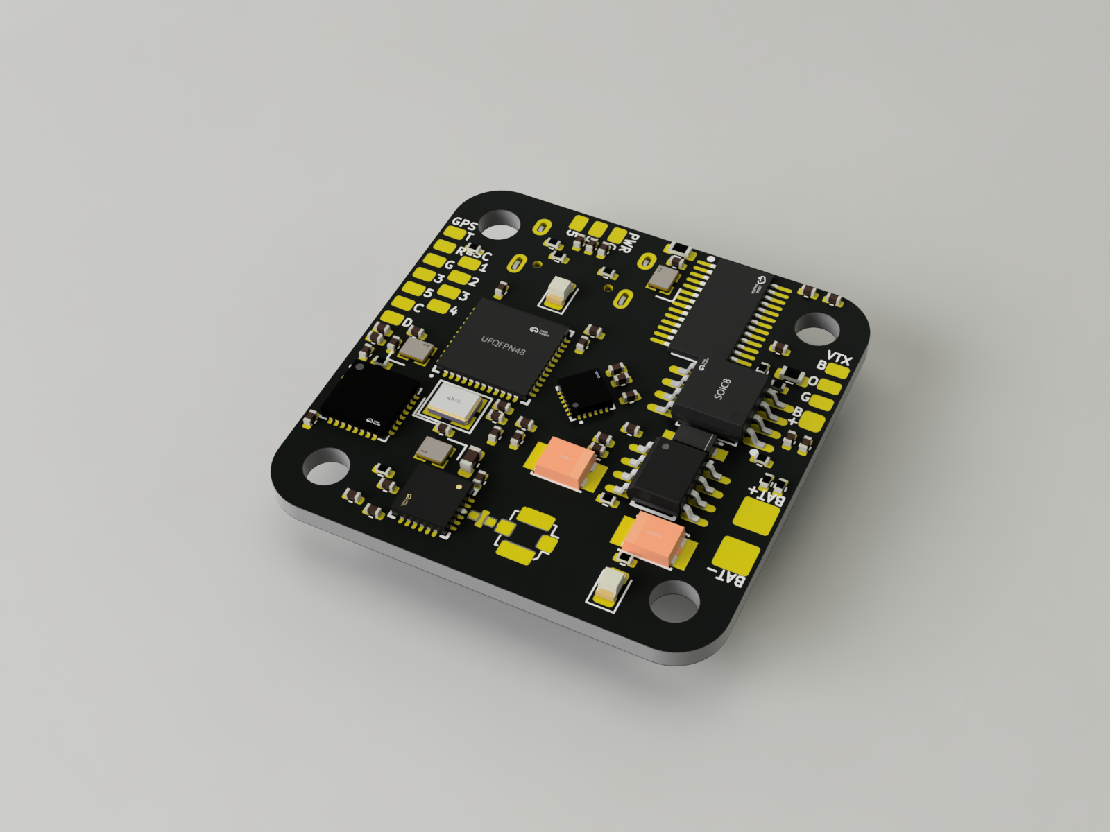 This is my custom AIO (No ESC) flight controller! I started this project because commercial flight controllers get very expensive very quickly as you demand for more features like integrated radio receivers. I took on the challenge of designing my own betaflight compatible flight controller and it was difficult especially since the board has only 2 layers to save as much cost as possible and it's also my first time working with RF in circuits.
This flight controller is designed for a wide range of drones from 2" to as big as you want it to, and supports battery voltage from 2s to 8s although it is recommended to use a maximum of 6s. The 25.5mm pattern should be compatible with almost all frames on the market
It also features many quality of life features like an integrated ExpressLRS (ELRS) 2.4GHz receiver, an onboard OSD which inserts telemetry directly into the FPV video feed, 16MB flash memory for flight & blackbox logging and a buzzer for identifying error codes and to locate the drone.
While the primary focus of this projet is the flight controller hardware and firmware, I have also included a guide for the full 3 inch long range / freestyle drone build that this board was designed for
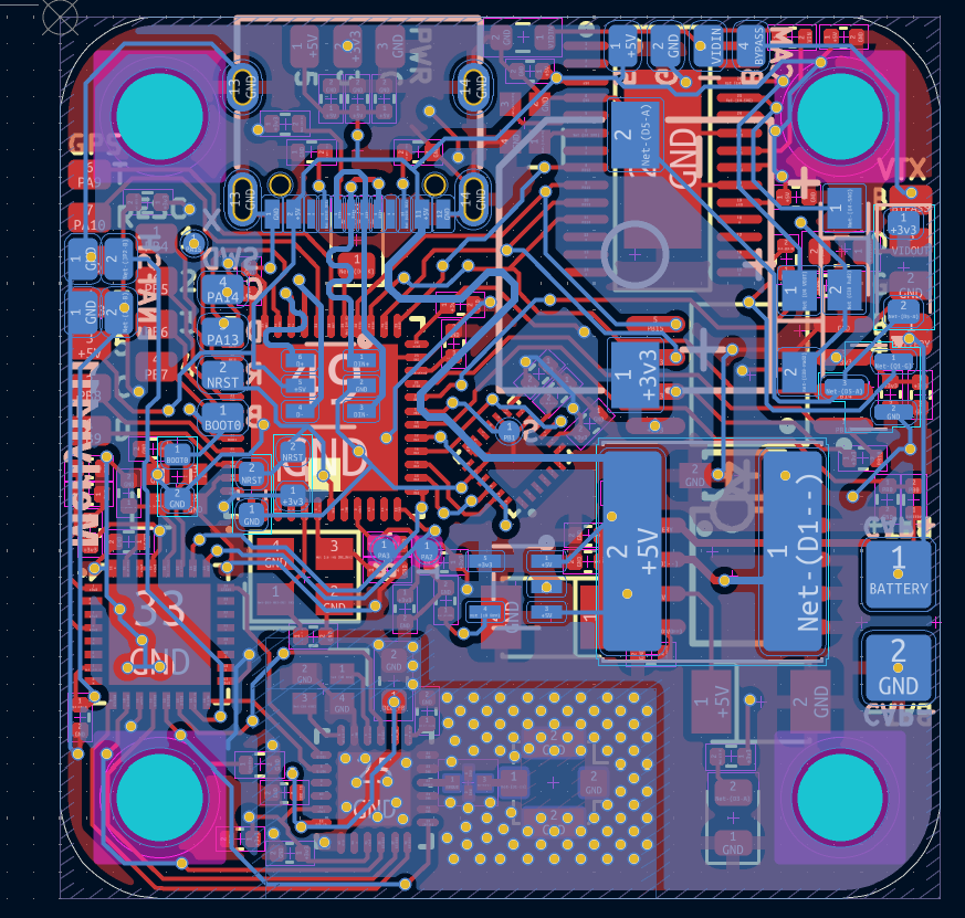
Note: The IMU should be in the forward facing direction if the USB C connector is facing forward and to the right. Adjust the mounting orientation accordingly in betaflight
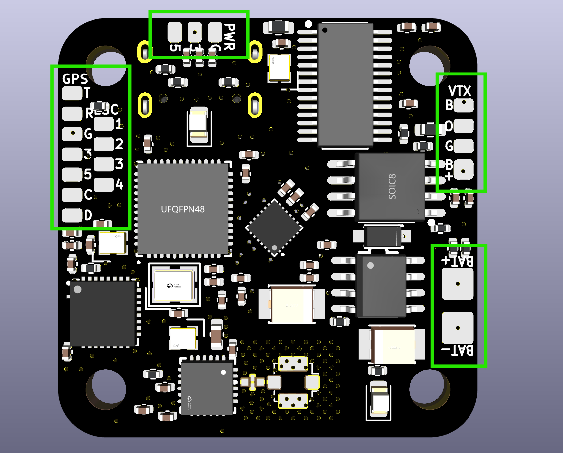
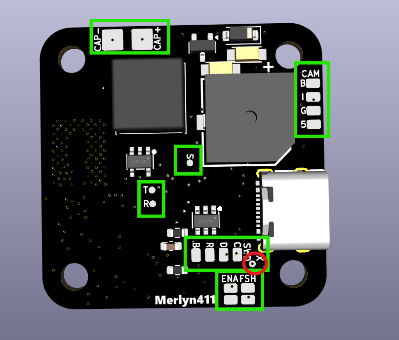
| Header | Pin Name | STM32 Pin | Description |
|---|---|---|---|
| GPS | T | PA9 | UART1 TX (Connect to GPS RX) |
R | PA10 | UART1 RX (Connect to GPS TX) | |
3 | - | 3.3V Power Out | |
5 | - | 5V Power out | |
G | - | Ground | |
C | PB8 | I2C1 SCL (For Magnetometer) | |
D | PB9 | I2C1 SDA (For Magnetometer) | |
| VTX | B | - | Video Bypass (Direct from camera) |
O | - | Analog Video Out (From AT7456E) | |
G | - | Ground | |
B+ | - | Battery Output | |
| CAM | B | - | Video Bypass (Direct to VTX) |
I | - | Analog Video Input (From camera) | |
G | - | Ground | |
5 | - | 5V Power Out | |
| SWD | C | PA14 | SWCLK (Debug & Flash) |
D | PA13 | SWDIO (Debug & Flash) | |
R | NRST | NRST (Debug & Flash) | |
B | BOOT0 | BOOT0 (Debug & Flash) | |
| ESC | 1-4 | PB4-PB7 | Motor Signal Outputs |
| BAT | BAT+ | - | Battery Positive Input |
BAT- | - | Battery Negative Input | |
| CAP | CAP+ | - | Capacitor Anode |
CAP- | - | Capacitor Cathode | |
| PWR | G | - | Ground |
3 | - | 3.3V Power Out | |
5 | - | 5V Power Out | |
| Test Points | X | PA15 | SmartAudio (Softserial 1 TX) |
S | PA15 | Current Sense Pin (From ESC) | |
T | PA2 | ESP8285 RX Pin (STM32 TX PIN) | |
R | PA3 | ESP8285 TX Pin (STM32 RX PIN) |
Because this is a custom hardware layout, I believe that there is no standard targets that has the exact pin mapping as my flight controller. You must compile the firmware with the custom target definition in /firmware/MERLYN411 or use the pre compiled firmware in /firmware/COMPILED.
[!TIP] You can use flash another target to the flight controller and use betaflight CLI to remap the pin resource, however this is not recommended as the chosen target might not be compiled with a feature that this flight controller supports.
make configs (install any required GCC toolchain if required)MERLYN411 and paste config.h in the new directorymake MERLYN411 and the .hex file should appear in betaflight/objB pad to 3.3v on the FC and plug in the USB C cable. Open Betaflight Configurator, select your compiled local .hex file, and click Flash Firmware.D, C, and D (R is optional) pads and flash via STM32CubeProgrammer.The internal ESP8285 and SX1281 receiver is wired to the STM32 via a hardware UART. It uses the standard BETAFPV 2.4GHz Lite RX firmware target. You can obtain the firmware binaries from the ELRS site or from this repository in /firmware/COMPILED. There's two way to flash the receiver:
Note that betaflight must be installed and configured before passthrough works
ReceiverBETAFPV 2.4GHz Lite RX target and press nextIf the ESP8285 is bricked or passthrough fails, you can flash it directly using an FTDI adapter or another ESP8285/ESP8286/ESP32 or even an arduino
Wiring the FTDI:
The UART pads on the board are named relative to the STM32's perspective. Because the STM32's TX is connected to the ESP8285's RX, you must wire your FTDI adapter RX to RX and TX to TX.
TX -> FC Pad TRX -> FC Pad RGND -> FC Pad G5V -> FC Pad 5 (or power via USB)You must disable the STM32 when flashing via the T and R pad
using an external FTDI as it will intefere with the UART lines. You can disable the STM32 by shorting the SWD R pad to ground. Remember to short the ENA pads on the bottom side to put the ESP8285 into flashing mode.
While this project is mainly focused on the Merlyn411 flight controller, I designed it along with a high efficiency 3 inch cruiser drone in mind. If you want to recreate the full build, below is the component breakdown and assembly steps
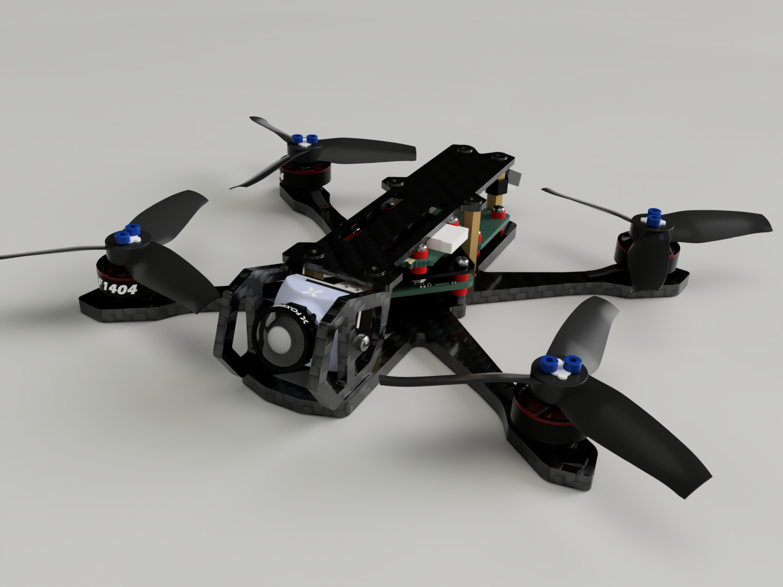
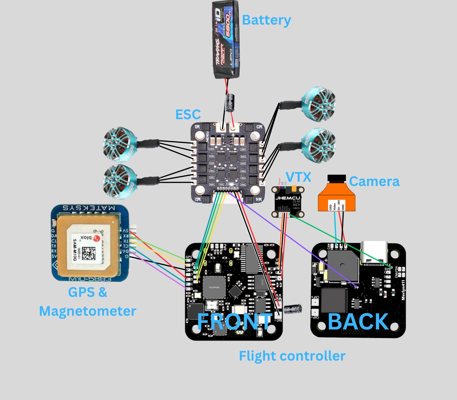
Currently, I am using a custom frame that I 3D printed for prototyping. I strongly advise against using a 3D printed frame for your final build. The Merlyn411 uses the MPU6500 IMU, which is sensitive to mechanical noise and vibrations. 3D printed frames will flex and resonate significantly more than carbon fiber frames. This flexing will send noise into the gyro and resulting in terrible flight performance. Also the 3D printed frame will likely not survive a moderate impact.
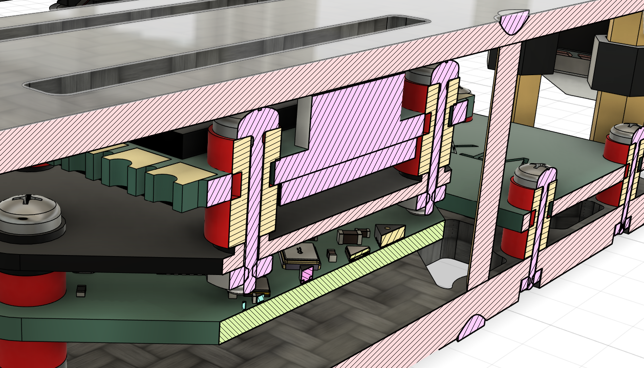
Because this is a custom stack with a 25.5mm FC and a 20mm ESC, the stack up is very specific. You will need:
The Merlyn411 uses a 25.5x25.5mm mounting pattern (which is meant for AIO boards). However, I needed a standalone ESC which comes in standard sizes like 20x20mm.
To make these fit together, you must use a 3D printed adapter plate in /production/3dPrint/boardAdapter.stl.
Stack Assembly Layer 1:
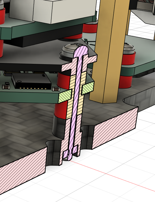
Stack Assembly Layer 2:
The JHEMCU 600mW VTX mounts to the rear of the frame.
Note: The prices in USD are converted as of 31 March 2026 and prices may fluctuate. The requested funding is $200 as a buffer for the unstable prices. Any unused funds is returned.
| Item Name | Link | Vendor | Quantity | Total Price (USD) |
|---|---|---|---|---|
| 2450FM07D0034 | Link | AliExpress | 1 | 6.40 |
| AliExpress Shipping | AliExpress | 1 | 3.15 | |
| PCB | JLCPCB | 1 | 2.00 | |
| PCB Assembly | JLCPCB | 1 | 79.49 | |
| JLCPCB Shipping | JLCPCB | 1 | 6.02 | |
| Sparkhobby 1303.5 5500KV motor | Link | Taobao | 4 | 22.50 |
| JHEMCU EM40A ESC | Link | Taobao | 1 | 18.11 |
| 19mm FPV Camera | Link | Taobao | 1 | 5.16 |
| JHEMCU 600mW VTX | Link | Taobao | 1 | 14.58 |
| M10 GPS & Magnetometer | Link | Taobao | 1 | 7.55 |
| Rubber Grommet Shock Mount | Link | Taobao | 12 | 0.80 |
| Gemfan 3016 | Link | Taobao | 1 | 1.75 |
| ELRS Dipole Antenna | Link | Taobao | 1 | 0.90 |
| Taobao Tax | Taobao | 1 | 8.35 | |
| Taobao Shipping | Taobao | 1 | 2.48 | |
| 10k Resistor | Link | Shopee | 1 | 0.45 |
| 100nF Capacior | Link | Shopee | 1 | 0.45 |
| 22uF Tantalum | Link | Shopee | 1 | 0.88 |
| USBCL6-2SC6 | Link | Shopee | 1 | 0.83 |
| 2N7002LT | Link | Shopee | 1 | 0.79 |
| 9650 Active Buzzer | Link | Shopee | 1 | 1.05 |
| SPX3819 | Link | Shopee | 1 | 1.45 |
| 8040 68uH Inductor | Link | Shopee | 1 | 1.51 |
| SPX Express Shipping | Shopee | 2 | 2.56 | |
| GRAND TOTAL | 189.21 |
| Qty | Value | Footprint | References |
|---|---|---|---|
| 17 | 0.1uF | Capacitor_SMD:C_0402_1005Metric | C2, C4, C11, C17, C23, C27, C28, C29, C34, C36, C37, C41, C44, C45, C47, C48 +1 |
| 6 | 10k | Resistor_SMD:R_0402_1005Metric | R3, R5, R12, R15, R16, R17 |
| 6 | 10uF | Capacitor_SMD:C_0402_1005Metric | C1, C7, C8, C10, C13, C49 |
| 5 | 10nF | Capacitor_SMD:C_0402_1005Metric | C12, C18, C24, C26, C38 |
| 4 | 5.1k | Resistor_SMD:R_0402_1005Metric | R1, R2, R6, R10 |
| 2 | 100uF | ELRSFC:CASE-B_3528 | C21, C35 |
| 2 | 10k | Resistor_SMD:R_0603_1608Metric | R4, R7 |
| 2 | 10pF | Capacitor_SMD:C_0402_1005Metric | C31, C33 |
| 2 | 12pF | Capacitor_SMD:C_0402_1005Metric | C42, C43 |
| 2 | 22uF | ELRSFC:CAP-SMD_L3.2-W1.6-RD-C7171 | C30, C32 |
| 2 | 75 | Resistor_SMD:R_0603_1608Metric | R8, R9 |
| 1 | 0.1uF | Capacitor_SMD:C_0603_1608Metric | C5 |
| 1 | 120 | Resistor_SMD:R_0402_1005Metric | R13 |
| 1 | 12k | Resistor_SMD:R_0402_1005Metric | R14 |
| 1 | 1N4148W | Diode_SMD:D_SOD-123 | D5 |
| 1 | 1uF | Capacitor_SMD:C_0402_1005Metric | C40 |
| 1 | 2.2uF | Capacitor_SMD:C_0402_1005Metric | C39 |
| 1 | 2450FM07D0034T | ELRSFC:FIL_2450FM07D0034T | FL1 |
| 1 | 25MHz | ELRSFC:CRYSTAL-SMD_4P-L3.2-W2.5-BL | X3 |
| 1 | 26MHz | ELRSFC:CRYSTAL-SMD_4P-L2.0-W1.6-BL | X4 |
| 1 | 27MHz | ELRSFC:CRYSTAL-SMD_4P-L2.0-W1.6-BL | X2 |
| 1 | 2N7002 | Package_TO_SOT_SMD:SOT-23 | Q1 |
| 1 | 470nF | Capacitor_SMD:C_0603_1608Metric | C25 |
| 1 | 47k | Resistor_SMD:R_0402_1005Metric | R11 |
| 1 | 52MHz | ELRSFC:CRYSTAL-SMD_4P-L2.0-W1.6-BL | X1 |
| 1 | 68uH | Inductor_SMD:L_Sunlord_SWPA8040S | L1 |
| 1 | AT7456E | ELRSFC:TSSOP-28_L9.7-W4.4-P0.65-LS6.4-BL-EP-2 | U4 |
| 1 | B5819W | ELRSFC:SOD-123_L2.7-W1.6-LS3.7-RD-1 | D1 |
| 1 | BAT | ELRSFC:BAT | H2 |
| 1 | BUZZER | ELRSFC:BUZ-SMD_L9.6-W9.6-LS10.0-R | BUZZER1 |
| 1 | CAM | ELRSFC:CAM | H4 |
| 1 | CAP | ELRSFC:CAP | H3 |
| 1 | Conn_Coaxial_Small | ELRSFC:UFL | J1 |
| 1 | ENA | ELRSFC:ENA | JP1 |
| 1 | ESC | ELRSFC:ESC | H8 |
| 1 | ESP8285H16 | ELRSFC:QFN-32_L5.0-W5.0-P0.50-TL-EP3.7 | U7 |
| 1 | EXTRA | ELRSFC:EXTRA | H9 |
| 1 | FLASH | ELRSFC:FLASH | JP2 |
| 1 | GPS | ELRSFC:GPS | H1 |
| 1 | GREEN | LED_SMD:LED_0805_2012Metric | D4 |
| 1 | MPU6500 | ELRSFC:QFN-24_L3.0-W3.0-P0.40-BL-EP | U5 |
| 1 | PWR | ELRSFC:PWR | H5 |
| 1 | RED | LED_SMD:LED_0805_2012Metric | D3 |
| 1 | SENSE | ELRSFC:SENSE | H10 |
| 1 | SPX3819M5-L-3-3/TR | ELRSFC:SOT-23-5_L3.0-W1.7-P0.95-LS2.8-BL | U9 |
| 1 | STM32F411CEU6 | ELRSFC:UFQFPN-48_L7.0-W7.0-P0.50-BL-EP | U6 |
| 1 | SWD | ELRSFC:SWD | H7 |
| 1 | SX1281IMLTRT | ELRSFC:QFN-24_L4.0-W4.0-P0.50-TL-EP2.6 | U8 |
| 1 | TYPE-C 16PIN 2MD(073) | ELRSFC:USB-C-SMD_TYPE-C-6PIN-2MD-073 | USB1 |
| 1 | USBLC6-2SC6 | ELRSFC:SOT-23-6_L2.9-W1.6-P0.95-LS2.8-BL | D2 |
| 1 | VTX | ELRSFC:VTX | H6 |
| 1 | W25Q128JVSIQTR | ELRSFC:SOIC-8_L5.3-W5.3-P1.27-LS8.0-BL | U1 |
| 1 | XL1509-5.0E1 | ELRSFC:SOIC-8_L5.0-W4.0-P1.27-LS6.0-BL | U2 |
The 92 most common of 98 parts.
It measures 33.3 × 33.3 mm and has 2 copper layers, 1.6 mm thick.
98 parts, built around the AT7456E, STM32F411CEU6, ESP8285H16 and SX1281IMLTRT. The full list of its parts is on this page, with links to each part's symbol and footprint where PCBKit's library has them.
From the YeetTheAnson/Merlyn411-FlightController repository on GitHub, at the commit this page was made from: the board is PCB/ELRSFC.kicad_pcb and its schematic PCB/ELRSFC.kicad_sch. PCBKit opens the board in the browser, with nothing to install.
Its repository states no licence, so its author keeps all rights: ask YeetTheAnson before reusing the design.
YeetTheAnson/Merlyn435-Flight-Stack
Successor to the Merlyn411 25mm flight controller. The flight stack includes a 3in1 20mm flight controller and a 20mm ESC.


Paschalis/UAV-TelemetryLink
Receiver and transmitter solution for GCS using ELRS, mLRS, and MAVLink for reliable telemetry and control.

Paschalis/fc-plus-sensor-module
FC Plus is a modular add-on board for UAV flight controllers, providing advanced telemetry, GPS, object avoidance (ToF, Sonar, IR), and LED indicators for status feedback.

OpenDrone-hw/OpenAIO
Open-source AIO for 2-6S toothpick quads: flight controller, 4-in-1 AM32 ESC and ExpressLRS receiver, 25.5x25.5 mm.

OpenDrone-hw/OpenRX-Lite
Open-source 2.4 GHz ExpressLRS receiver with an on-board ceramic antenna.

aprskalo1/nano24-elrs-receiver
nano24: compact 2.4 GHz ExpressLRS receiver prototype with ESP32-C3, SX1281, CRSF and a printed Wi-Fi antenna. KiCad sources, BOM, Gerbers and validation notes.

bastian2001/Kolibri-FC-Hardware
Hardware for the Kolibri Flight Controller. 30mm/20mm FC with RP2350 + ELRS onboard