
2 layers74.4 × 51.2 mm
Esp32-wroom timer
AlessandroAU/Chorus32-ESP32LapTimer
This is an ESP32 port of the popular Chorus RF Laptimer
66 parts102GPL-3.0

 yedidia-sisay/BluePill-USB-C
An open-source STM32F103C8T development board with **USB-C** power input, designed in KiCad. A modern take on the classic "Blue Pill" form factor — replacing the fragile Micro-USB with a robust USB-C connector and adding ESD protection, power indication LED, and clean breakout headers.
Stm32 first is an open-source printed circuit board by yedidia-sisay, from the yedidia-sisay/BluePill-USB-C repository on GitHub, published under the CERN-OHL-P-2.0 licence. It is a 2-layer board of 51.3 × 26 mm with 33 parts on 49 nets, routed with 182 tracks and 34 vias.
It is built around the AMS1117. Its parts include 13 capacitors, 7 resistors, 3 diodes, 3 connectors and 2 ICs. It belongs with the interfaces and adapters and microcontroller boards boards and the STM32 boards of this library.
An open-source STM32F103C8T development board with USB-C power input, designed in KiCad. A modern take on the classic "Blue Pill" form factor — replacing the fragile Micro-USB with a robust USB-C connector and adding ESD protection, power indication LED, and clean breakout headers.
Contributions are welcome as I am trying to build a portfolio of good hardware projects, that people can use as a reference when learning and designing there own projects.
Yedidia Sisay Semay Project · Rev V0.1
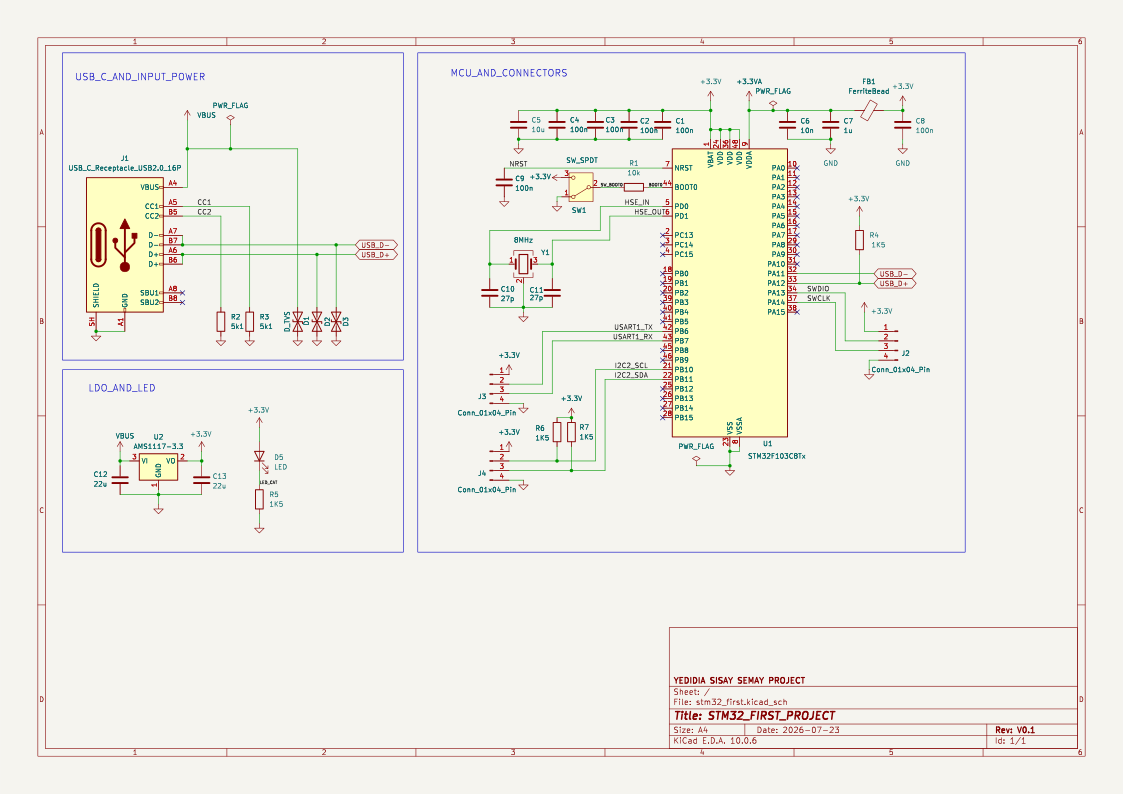
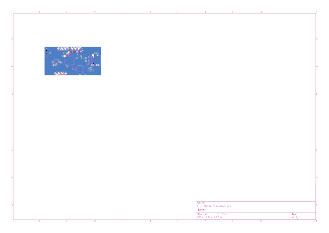
| Ref | Value | Description | Qty |
|---|---|---|---|
| U1 | STM32F103C8Tx | ARM Cortex-M3 MCU, LQFP-48 | 1 |
| U2 | AMS1117-3.3 | 3.3 V LDO voltage regulator | 1 |
| J1 | USB_C_Receptacle_USB2.0_16P | USB Type-C receptacle | 1 |
| J2 | Conn_01x04_Pin | SWD/JTAG debug header | 1 |
| J3, J4 | Conn_01x04_Pin | GPIO breakout headers | 2 |
| Y1 | 8 MHz | Crystal oscillator (4-pin, GND) | 1 |
| FB1 | FerriteBead | Analog supply filter | 1 |
| SW1 | SW_SPDT | BOOT0 / Reset select switch | 1 |
| C1–C4, C8, C9 | 100 nF | Decoupling capacitors | 6 |
| C5 | 10 µF | Bulk decoupling | 1 |
| C6 | 10 nF | Analog decoupling | 1 |
| C7 | 1 µF | Analog decoupling | 1 |
| C10, C11 | 27 pF | Crystal load capacitors | 2 |
| C12, C13 | 22 µF | LDO input/output capacitors | 2 |
| R1 | 10 kΩ | NRST pull-up | 1 |
| R2, R3 | 5.1 kΩ | USB-C CC pull-down resistors | 2 |
| R4–R7 | 1.5 kΩ | LED current-limit / USB pull-up | 4 |
| D1–D3 | D_TVS | ESD protection (USB lines) | 3 |
| D5 | LED | Power indicator | 1 |
The schematic is organized into clear functional blocks:
git clone https://github.com/yedidia-sisay/BluePill-USB-C.git
cd BluePill-USB-C
Open stm32_first.kicad_pro in KiCad to view/edit the hardware design.
Connect an SWD debugger to the J2 header and flash via STM32CubeIDE, or use st-flash / OpenOCD from the command line.
BluePill-USB-C/
├── stm32_first.kicad_pro        # KiCad project file
├── stm32_first.kicad_sch        # Schematic
├── stm32_first.kicad_pcb        # PCB layout
├── HRO_TYPE-C-31-M-12.step      # USB-C connector 3D model
├── images/
│   ├── schematic.svg            # Schematic export
│   └── board.svg                # PCB layout export
├── stm32/                       # Firmware project (STM32CubeIDE)
│   ├── Src/main.c               # Application entry point
│   ├── Startup/                  # ARM startup assembly
│   └── STM32F103C8TX_FLASH.ld   # Linker script
├── LICENSE                       # CERN-OHL-P-2.0
└── README.md # This file| Decision | Rationale |
|---|---|
| USB-C instead of Micro-USB | Mechanical durability, reversible plug, modern standard |
| AMS1117-3.3 LDO | Widely available, cheap, sufficient current for most applications |
| 5.1 kΩ CC resistors | Required for USB-C to negotiate default USB power (5 V / 500 mA) |
| TVS diodes on USB | Protect MCU from ESD events on exposed USB port |
| Ferrite bead on VDDA | Clean analog supply for ADC accuracy |
| 8 MHz HSE crystal | Enables precise 72 MHz system clock via PLL |
Contributions are welcome! Feel free to:
This project is licensed under the CERN Open Hardware Licence Version 2 — Permissive (CERN-OHL-P v2).
See LICENSE for the full text.
You are free to use, study, modify, and distribute this design. See the licence for details.
| Qty | Value | Footprint | References |
|---|---|---|---|
| 6 | 100n | Capacitor_SMD:C_0402_1005Metric | C1, C2, C3, C4, C8, C9 |
| 4 | 1K5 | Resistor_SMD:R_0402_1005Metric | R4, R5, R6, R7 |
| 3 | Conn_01x04_Pin | Connector_PinHeader_2.54mm:PinHeader_1x04_P2.54mm_Vertical | J2, J3, J4 |
| 3 | D_TVS | Diode_SMD:D_SOD-523 | D1, D2, D3 |
| 2 | 22u | Capacitor_SMD:C_0603_1608Metric | C12, C13 |
| 2 | 27p | Capacitor_SMD:C_0402_1005Metric | C10, C11 |
| 2 | 5k1 | Resistor_SMD:R_0402_1005Metric | R2, R3 |
| 1 | 10k | Resistor_SMD:R_0402_1005Metric | R1 |
| 1 | 10n | Capacitor_SMD:C_0402_1005Metric | C6 |
| 1 | 10u | Capacitor_SMD:C_0603_1608Metric | C5 |
| 1 | 1u | Capacitor_SMD:C_0603_1608Metric | C7 |
| 1 | 8MHz | Crystal:Crystal_SMD_3225-4Pin_3.2x2.5mm | Y1 |
| 1 | AMS1117 | Package_TO_SOT_SMD:SOT-223-3_TabPin2 | U2 |
| 1 | FerriteBead | Inductor_SMD:L_0603_1608Metric | FB1 |
| 1 | LED | LED_SMD:LED_0603_1608Metric | LED |
| 1 | STM32F103C8Tx | Package_QFP:LQFP-48_7x7mm_P0.5mm | U1 |
| 1 | SW_SPDT | Button_Switch_SMD:SW_SPDT_PCM12 | SW1 |
| 1 | USB_C_Receptacle_USB2.0_16P | Connector_USB:USB_C_Receptacle_HRO_TYPE-C-31-M-12 | USBC |
AlessandroAU/Chorus32-ESP32LapTimer
This is an ESP32 port of the popular Chorus RF Laptimer


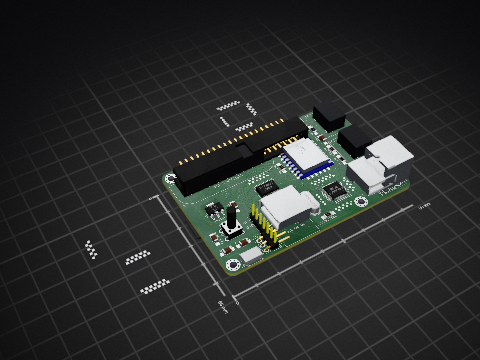
uli/basicengine-pcb
Schematics and PCB layout for the BASIC Engine home computer


MR-DOS/TDR_diploma_thesis
Time domain reflectometer. Includes Hardware, firmware and GUI in Octave. Also a diploma thesis.
It measures 51.3 × 26 mm and has 2 copper layers, 1.6 mm thick.
33 parts, built around the AMS1117. The full list of its parts is on this page, with links to each part's symbol and footprint where PCBKit's library has them.
From the yedidia-sisay/BluePill-USB-C repository on GitHub, at the commit this page was made from: the board is stm32_first.kicad_pcb and its schematic stm32_first.kicad_sch. PCBKit opens the board in the browser, with nothing to install.
Its repository publishes it under the CERN-OHL-P-2.0 licence: you may reuse it on that licence's terms (keep the author's notice, and for a copyleft licence share your changes alike).