
2 layers482.5 × 711 mm

Българска версия / Original Bulgarian internship log
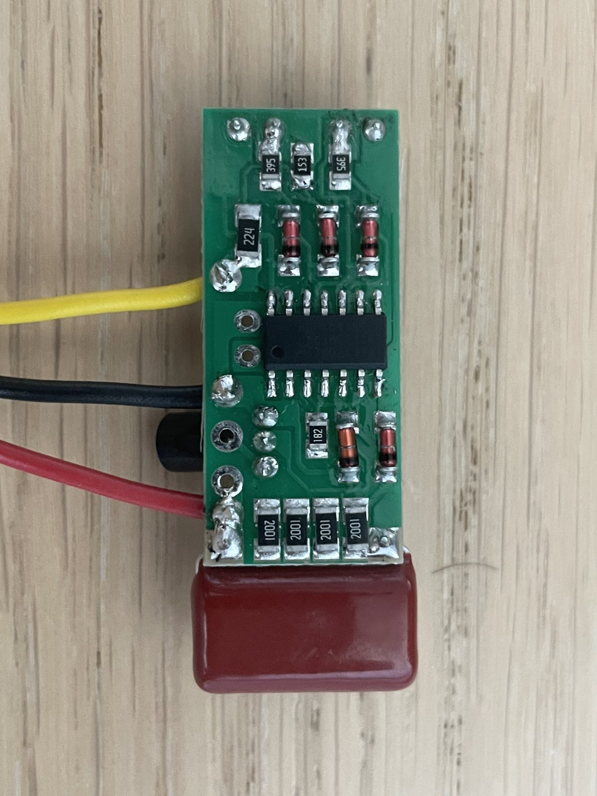
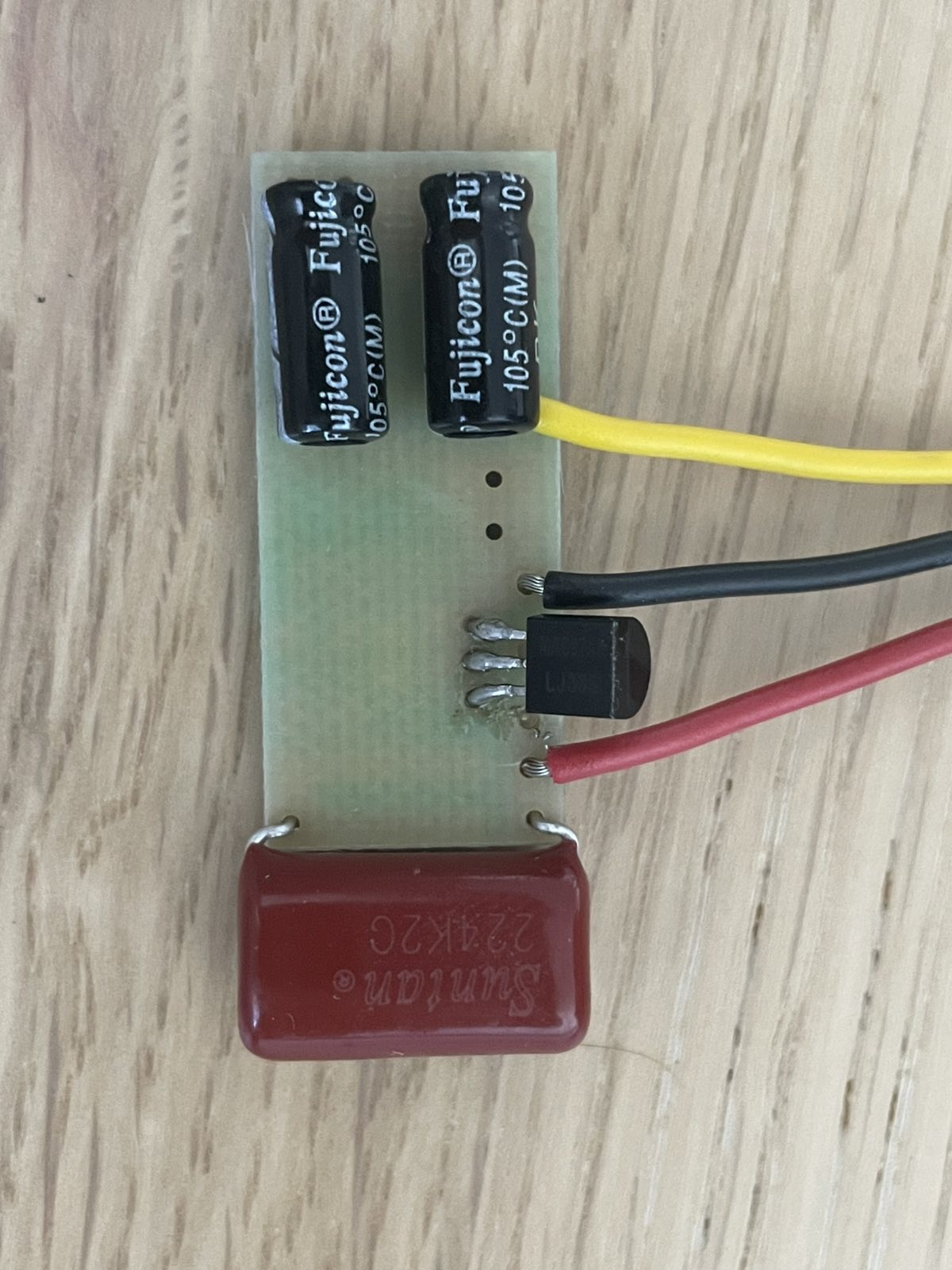
Fan is an open-source printed circuit board by yasenOfficial, from the yasenOfficial/ZekEng-Intern repository on GitHub. It is a 2-layer board of 32.5 × 14.5 mm with 26 parts on 18 nets, routed with 114 tracks and 0 vias.
It is built around the HEF4093BT, 1N4148WS and BZX84J-C12,115. Its parts include 9 resistors, 5 diodes, 3 capacitors and 1 IC.


Fan-controller reverse engineering, simulation, PCB redesign, humidity-sensor research, and embedded audio DSP development.
Българска версия / Original Bulgarian internship log
The main goal of this internship was to analyze and redesign an existing fan-controller board that was prone to failure. The work covered reverse engineering, LTspice simulation, component selection, schematic capture, PCB layout, fabrication, assembly, and supporting research into humidity sensing.
While the redesigned boards were being manufactured, the project was expanded with an embedded-audio task based on the Electrosmith Daisy platform. This included real-time reverb, audio passthrough, SD-card access, WAV parsing, and initial convolution-reverb development.
The original reverse-engineering files are available in Files for Reverse Engineering.
Fan/ — KiCad schematic, PCB layout, project backups, fabrication files, and schematic PDFLTSpice Files/ — LTspice tutorials, component tests, power-supply simulation, and fan-controller simulationFiles for Reverse Engineering/ — source material for the original boardHumSensorResearch/ — humidity-sensor material research and reference papersDaisyExamples/pod/ — Daisy Pod audio experiments and convolution projectImages/ — project photos, plots, screenshots, and supporting mediaREADME_BG.md — the original Bulgarian day-by-day internship logThe simulation work started with the LTspice workflow in LTSpice Files/TutorialRoman/TutorialRoman.asc, covering component placement, wiring, parameter assignment, directives, and signal analysis.
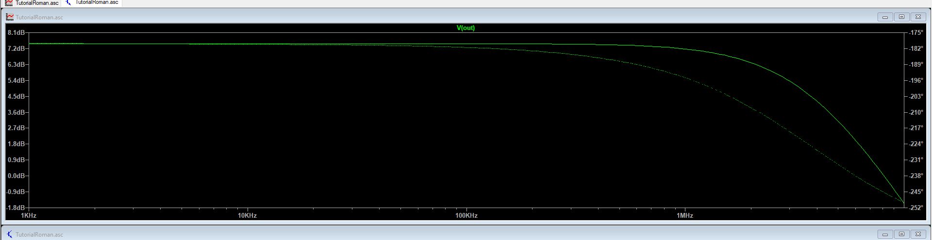
.ac dec 50 1k 10MegThis sweeps the circuit from 1 kHz to 10 MHz, using 50 logarithmically spaced points per decade, to measure gain and phase response.
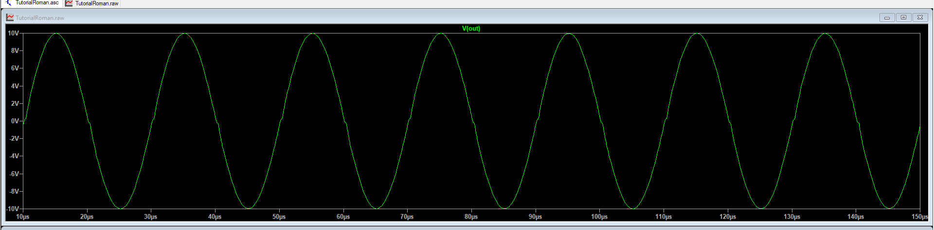
.tran 0 300u 100u 0.01uThis evaluates voltages and currents over 300 µs, starts saving data after 100 µs, and limits the maximum timestep to 0.01 µs.
.four 500k 10V(out)The transient output is decomposed into harmonics around a 500 kHz fundamental to assess signal quality.
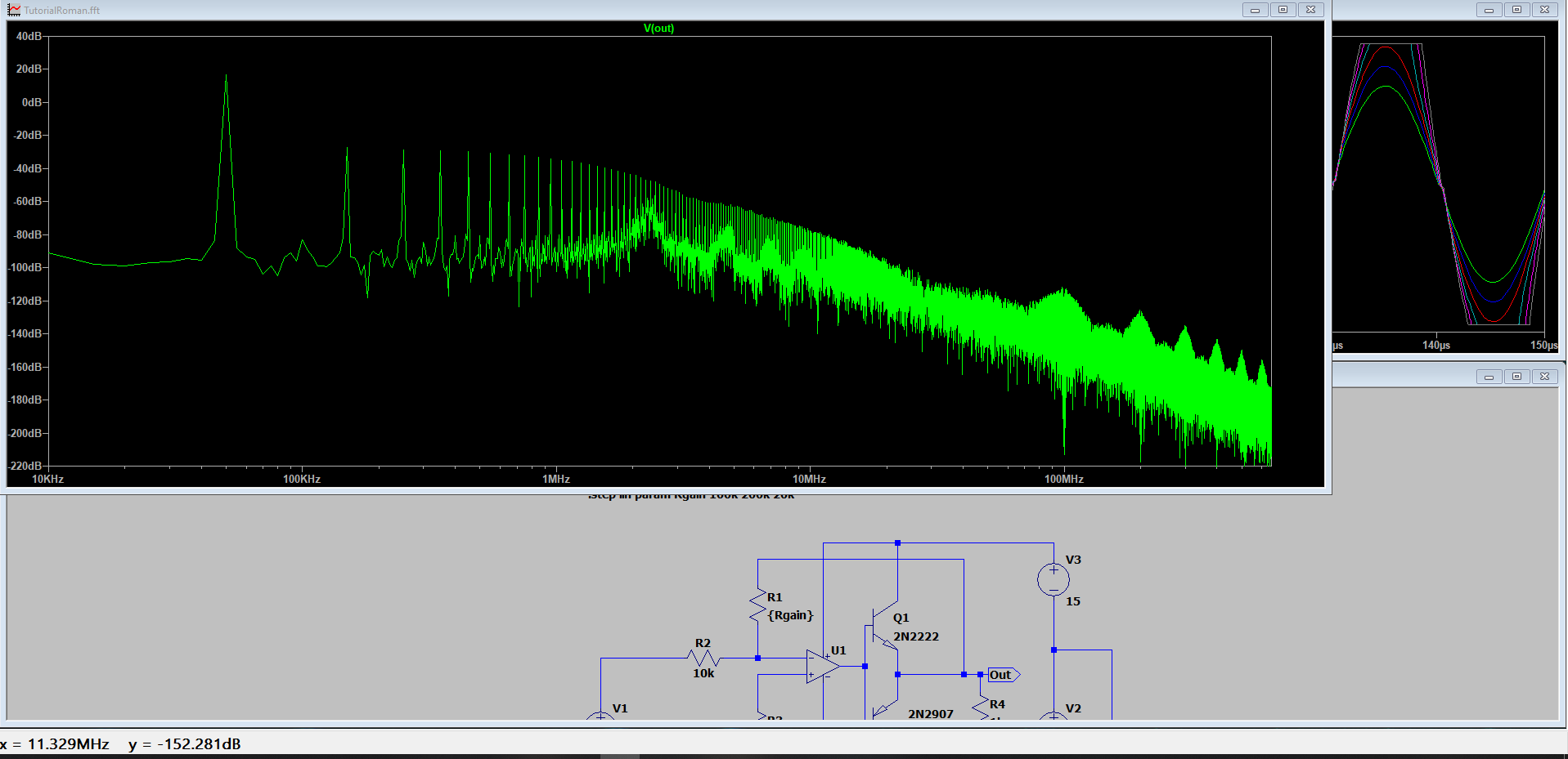
.step lin param Rgain 100k 200k 20kRgain is swept from 100 kΩ to 200 kΩ in 20 kΩ increments, with the analyses repeated for every value.
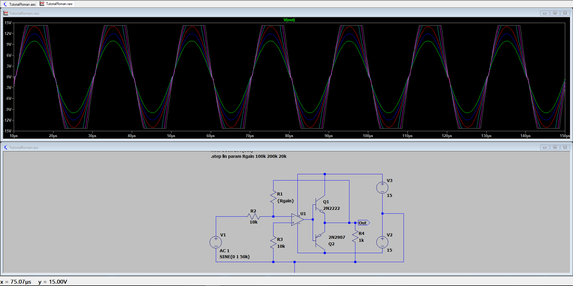
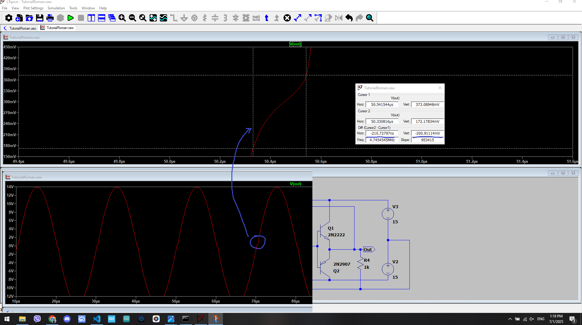
The transient simulation revealed a point at which the output departed from the expected sine wave. Cursor measurements showed that the operational amplifier required measurable time to overcome the combined VBE voltage drop of transistors Q1 and Q2. Of the six simulated cases, the third trace—R1 = 140 kΩ, with a 14 V amplitude—was the minimum acceptable result.
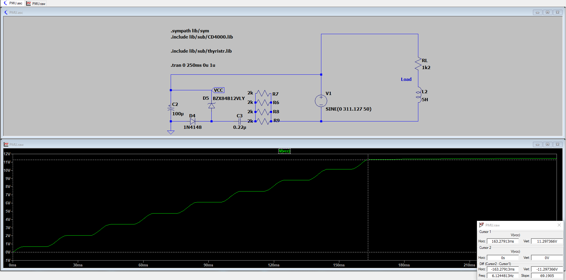
The CD4000-series models and the MAC97A8 triac model were added to the LTspice project. Supporting tests include:
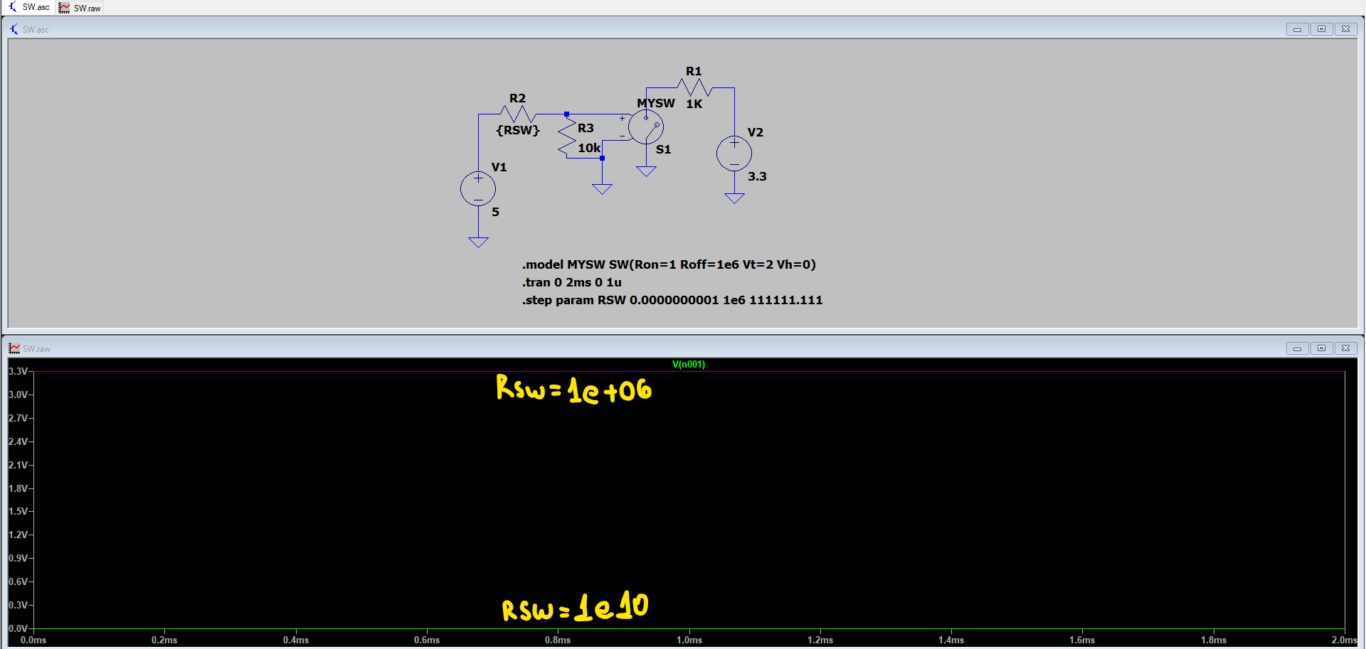
NAND Tests.asc — CD4093B NAND-gate test with a 12 V-amplitude sine waveSW.asc — LTspice voltage-controlled switch experimentsPMU.asc — power-supply simulationVentilator.asc — complete fan-controller simulation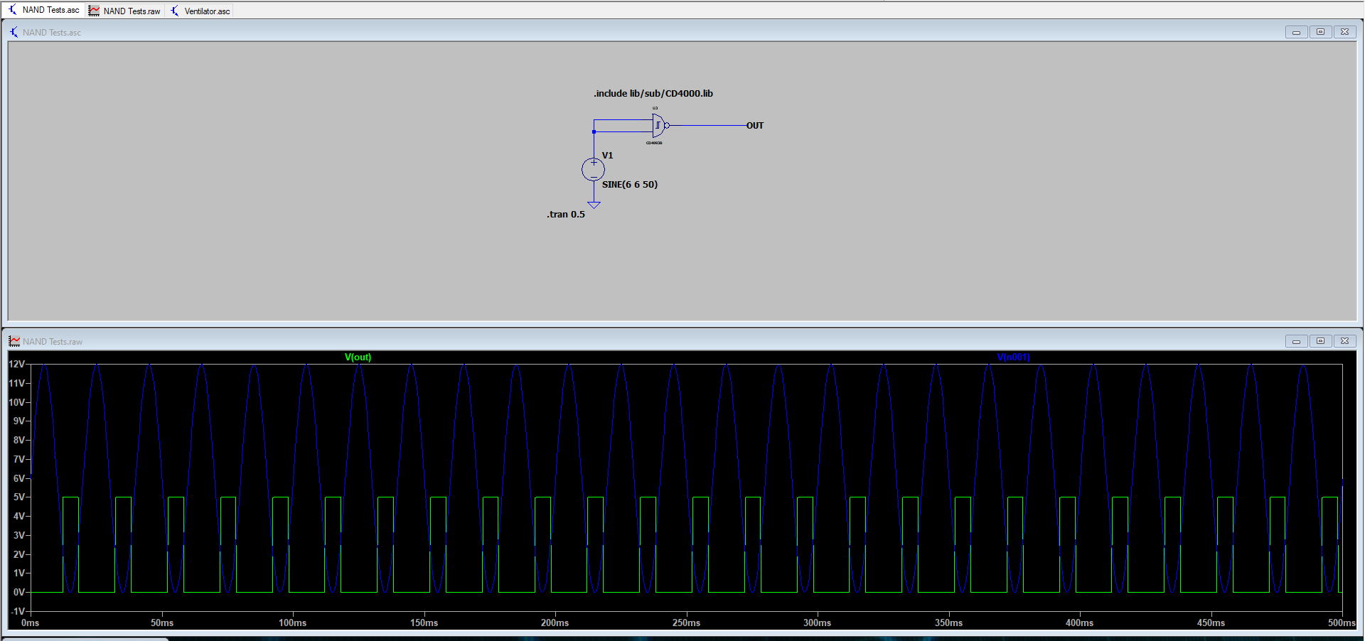
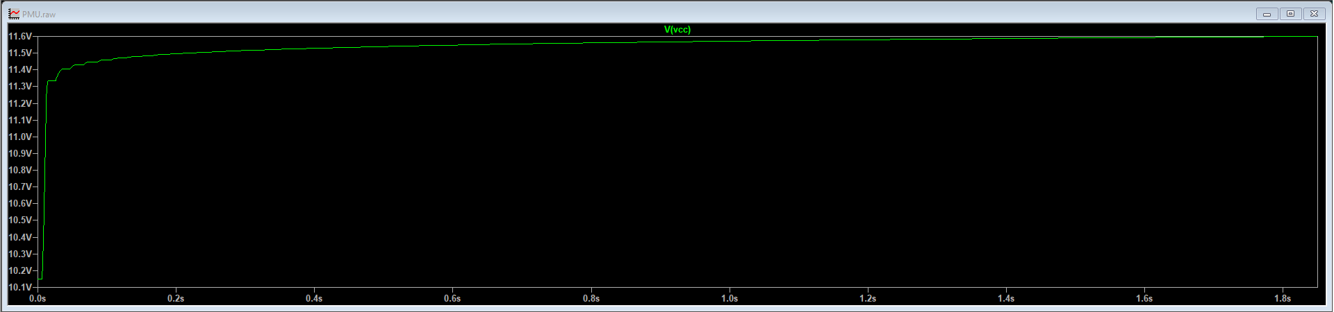
The simulated supply reaches approximately 11.3 V after 160 ms and then gradually rises to about 11.6 V within two seconds.
The board was recreated in KiCad and revised to improve reliability while retaining the original mechanical constraints of approximately 14.5 mm × 32.5 mm.
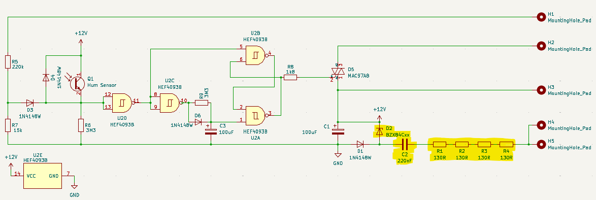
The PCB work included:
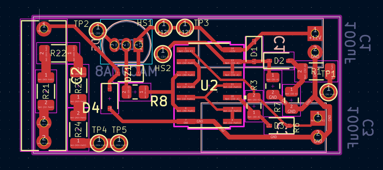
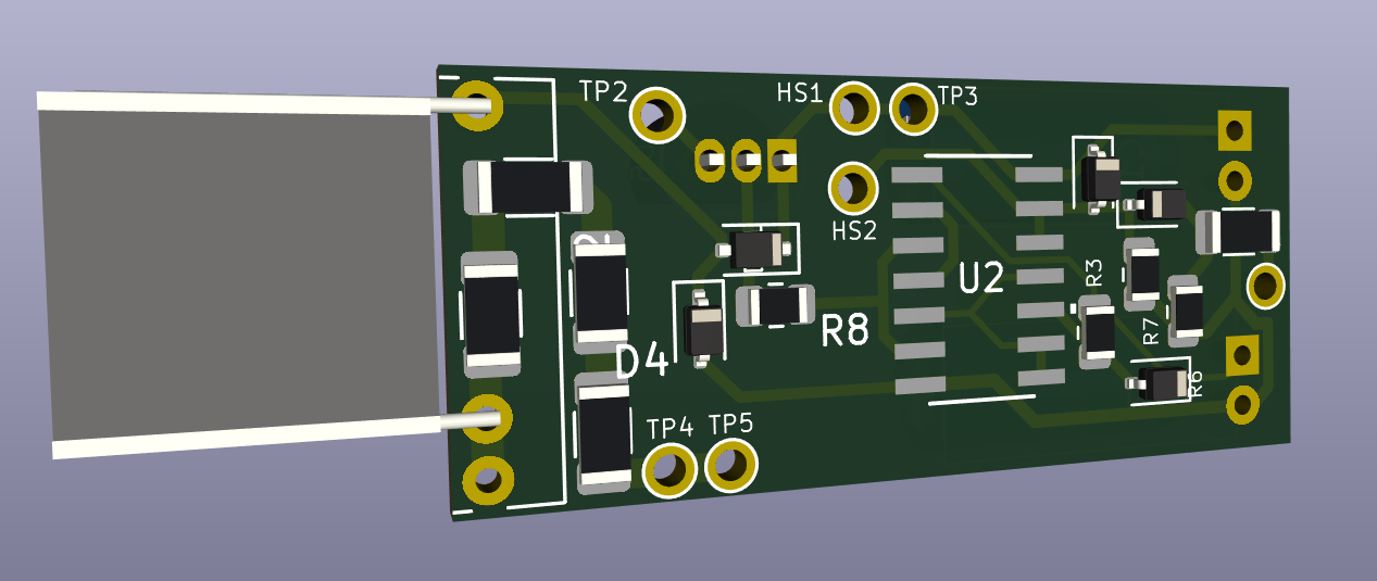
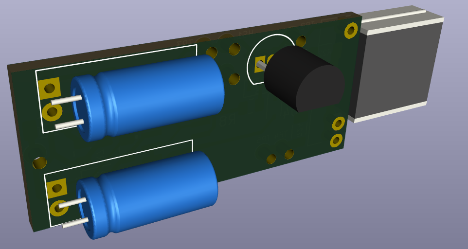
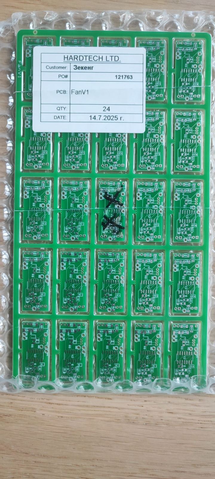
After review, Gerber fabrication files were exported to Fan/Gerbers.zip, and the prototype was sent to Hardtech for production. A bill of materials was also prepared, including cost estimates for prototype quantities of 25 boards and mass production at 1,000 boards.
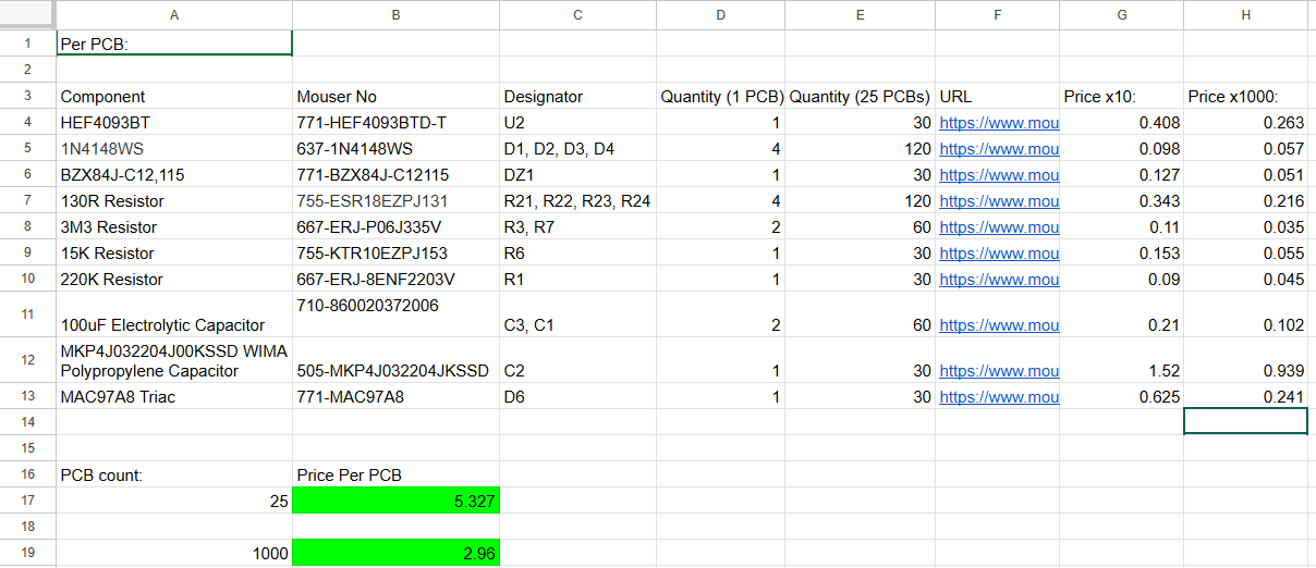
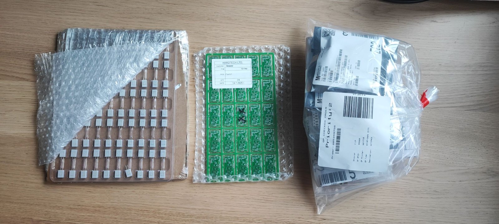
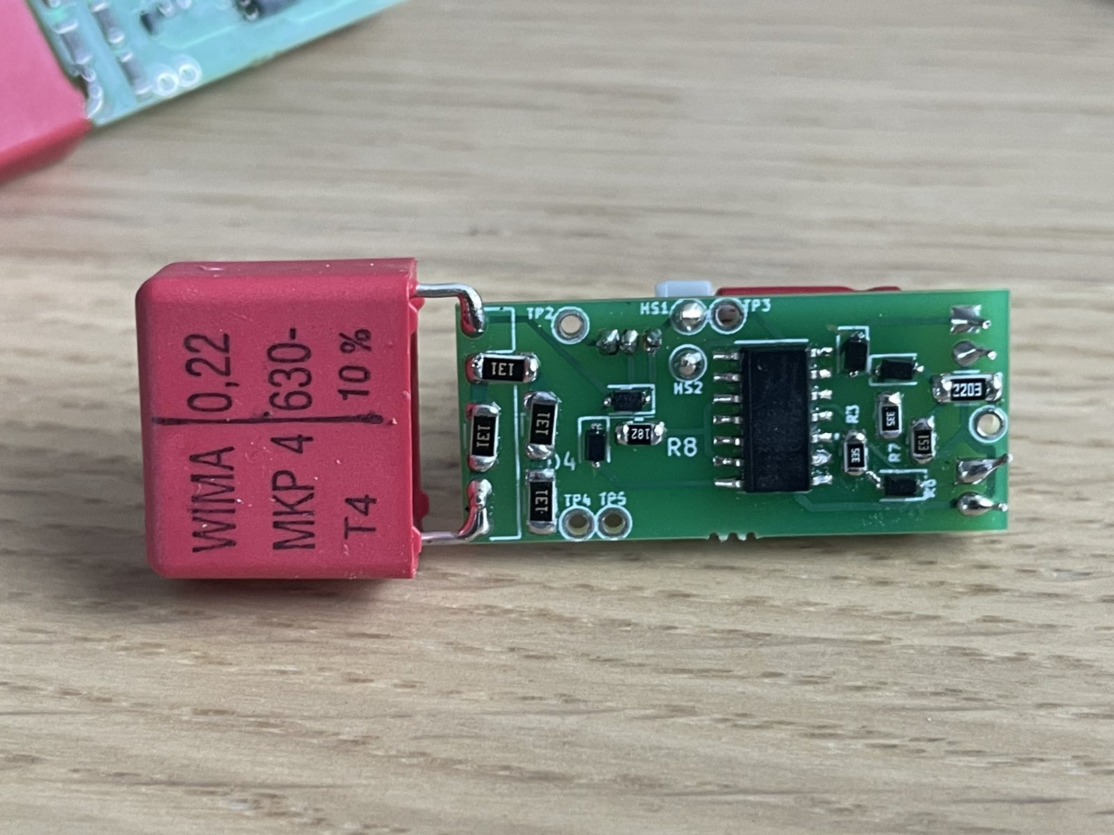
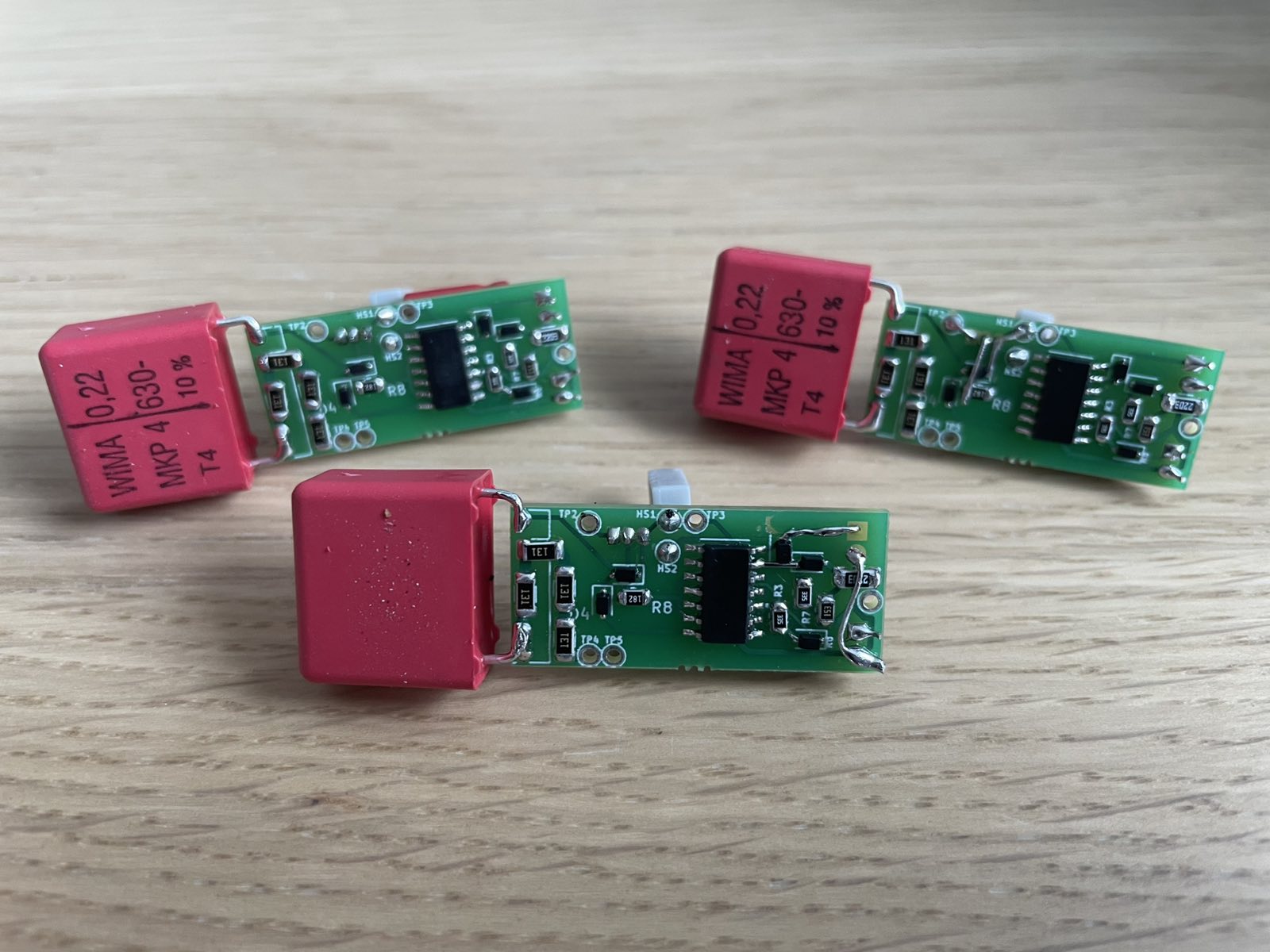
The boards and components were received and three prototypes were assembled for evaluation.
The original resistive humidity sensor was coated with latex, which degraded when exposed to moisture. Several hydrophilic sensing materials were investigated:
Measurements from the original sensor indicated a nominal resistance of approximately 1.8 MΩ, falling to around 1 MΩ at 100% relative humidity. A major obstacle was the lack of reliable resistance-versus-area data for candidate coatings at a defined thickness.
To avoid this uncertainty, a commercial HR202 humidity sensor was removed from another fan, evaluated, and selected for the redesign.
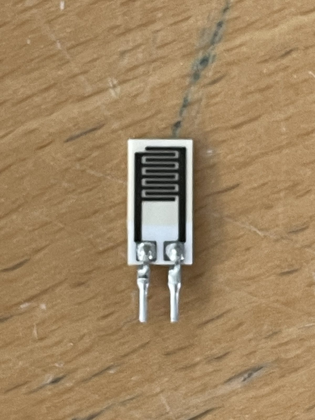
Reference material is stored in HumSensorResearch/, including Polyaniline_based_impedance_humidity_sen.pdf.
While waiting for PCB fabrication, an Electrosmith Daisy development board was configured using the official C++ development-environment guide.
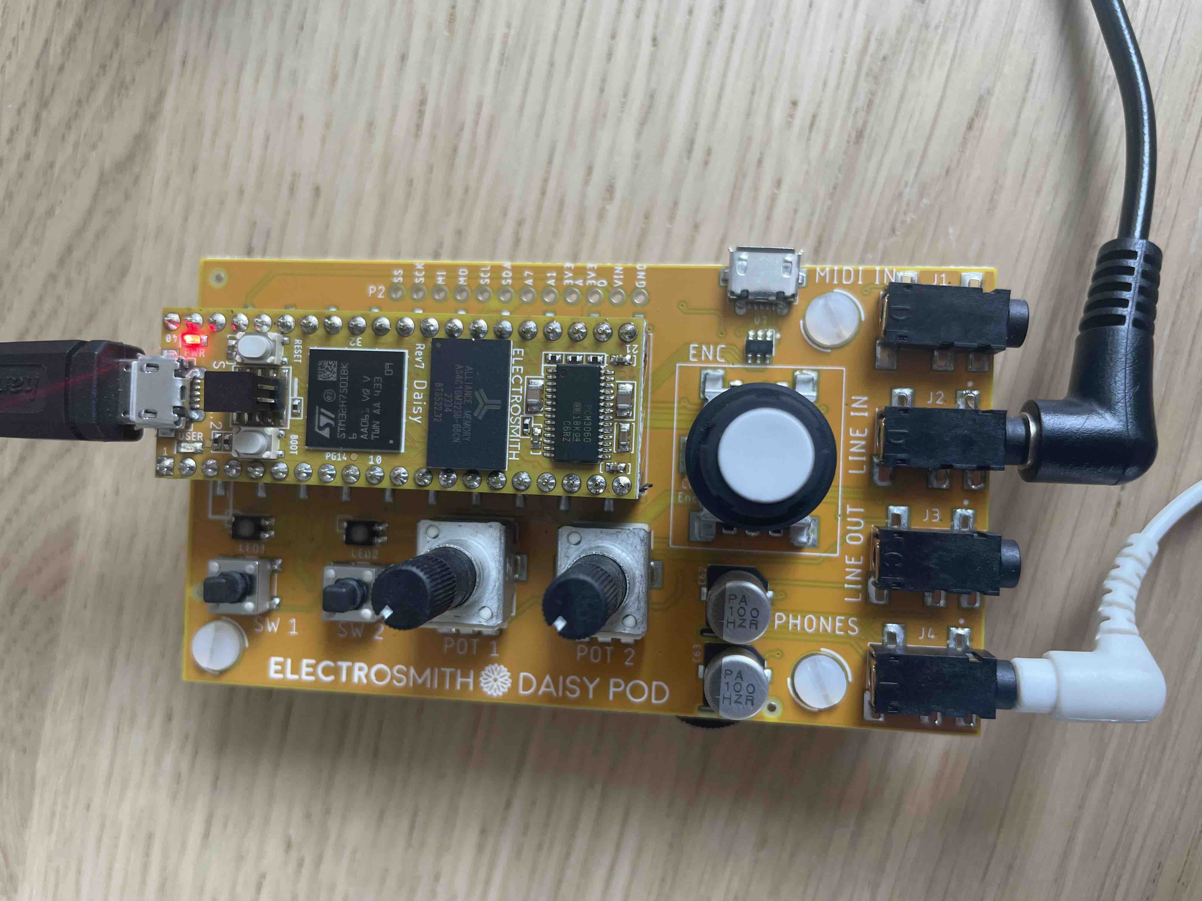
The following Daisy Pod examples were developed:
Reverb — generates a signal and applies reverbPassthrough — routes computer audio through the board to the headphone output without processingPassthroughReverb — applies reverb to the passthrough signalConvolution — WAV loading, parsing, and convolution-reverb developmentDemonstrations:
The convolution goal was to load an impulse-response WAV file from an SD card and reproduce the acoustic response on the incoming audio signal. The tunnel-entrance impulse response is stored under DaisyExamples/pod/Convolution/deprecated/mono files/.
The source file was prepared with SoX:
sox tunnel_entrance_f_1way_mono.wav -r 48000 -b 24 -c 1 tunnel_entrance_48k.wav gain -n -3 rate -vThis converts the file to the Daisy board's native 48 kHz sample rate, uses a mono 24-bit output, normalizes the peak to −3 dBFS, and enables SoX's high-quality resampling filter.
Back-to-back PrintLine calls caused serial output to stall. A short delay provided an initial workaround:
hw.DelayMs(1);A proper Flush() method was then added to the libDaisy logger and the library was rebuilt:
template <LoggerDestination dest>
void Logger<dest>::Flush()
{
    if(tx_ptr_ > 0)
    {
        TransmitBuf();
    }
    tx_ptr_ = 0;
}After resolving file-access issues, the firmware successfully opened the SD-card file and verified its bytes against a hex viewer.
A WAV file is a RIFF container, so the audio data chunk is not guaranteed to begin at byte 37. Tools may insert chunks such as LIST or bext before the audio payload. The parser was therefore changed to scan dynamically for both the fmt and data chunks instead of assuming fixed offsets.
A successfully parsed test file reported:
RIFF: RIFF
File size: 480072
WAVE: WAVE
fmt : fmt
Audio Format: 1
Channels: 1
Sample Rate: 48000
Byte Rate: 96000
Block Align: 2
Bits Per Sample: 16
data: data
Data Size: 480002
Data Offset: 78
The WAV handling code was separated from main, and FatFs FIL objects were moved to global storage after debugging initialization problems with local instances. A file-copy routine was implemented to read and rewrite both the WAV header and sample data, providing a way to validate the SD-card data before integrating it into the convolution pipeline.
| Qty | Value | Footprint | References |
|---|---|---|---|
| 7 | TestPoint | Pads:TestPoint_Top_Hole_D1.8x1.1mm | HS1, HS2, TP1, TP2, TP3, TP4, TP5 |
| 4 | 130R | Resistor_SMD:R_1206_3216Metric | R21, R22, R23, R24 |
| 4 | 1N4148WS | Diode_SMD:D_SOD-323 | D1, D2, D3, D4 |
| 2 | 100uF | Capacitors:C_Radial_D5.0mm_H11.0mm_P2.00mm_Lying | C1, C3 |
| 2 | 3M3 | Resistor_SMD:R_0805_2012Metric | R3, R7 |
| 1 | 15k | Resistor_SMD:R_0805_2012Metric | R6 |
| 1 | 1k8 | Resistor_SMD:R_0805_2012Metric | R8 |
| 1 | 220k | Resistor_SMD:R_1206_3216Metric | R1 |
| 1 | 220nF | Capacitors:C_Rect_L11.5mm_W4.5mm_P10.00mm_MKT_DoublePad | C2 |
| 1 | BZX84J-C12,115 | Diode_SMD:D_SOD-323F | DZ1 |
| 1 | Generic_Triac_A2GA1 | Package_TO_SOT_THT:TO-92_Inline | D6 |
| 1 | HEF4093B | CD4093:D14 | U2 |


formulaslug/fs-3-schematics
Electrical Design Repository for fs-3 schematics and PCBs


fordp2002/music2xxx
A clone of the Hybrid Music2000 Midi interface for the Acorn BBC Microcomputer
It measures 32.5 × 14.5 mm and has 2 copper layers, 1.6 mm thick.
26 parts, built around the HEF4093BT, 1N4148WS and BZX84J-C12,115. The full list of its parts is on this page, with links to each part's symbol and footprint where PCBKit's library has them.
From the yasenOfficial/ZekEng-Intern repository on GitHub, at the commit this page was made from: the board is Fan/Fan.kicad_pcb and its schematic Fan/Fan.kicad_sch. PCBKit opens the board in the browser, with nothing to install.
Its repository states no licence, so its author keeps all rights: ask yasenOfficial before reusing the design.