

2 layers111.5 × 102 mm
Wall e
c-lydia/ESP-ROS2
A tiny robot with IMU (MPU5060) and an ultrasonic sensor (HC-SR04), running on micro-ROS, communicating over UDP.
12 parts2Apache-2.0
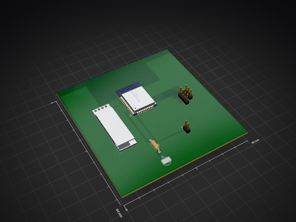
 yagiz-bas/ESP32-Smart-Target-Detection-System
A compact ESP32-based target detection and alarm system using an HC-SR04 ultrasonic sensor, an SG90 servo, an SSD1306 OLED display, a buzzer, and a red LED.
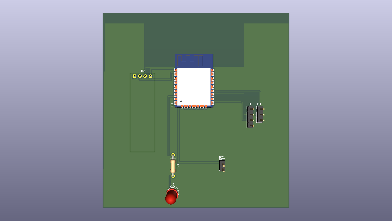
ESP32 Radar System is an open-source printed circuit board by yagiz-bas, from the yagiz-bas/ESP32-Smart-Target-Detection-System repository on GitHub. It is a 2-layer board of 90 × 94 mm with 7 parts on 38 nets, routed with 104 tracks and 1 via.
It is built around the ESP32-WROOM-32 and HC-SR04. Its parts include 2 ICs, 1 resistor, 1 diode and 1 connector. It belongs with the ESP32 boards of this library.
A compact ESP32-based target detection and alarm system using an HC-SR04 ultrasonic sensor, an SG90 servo, an SSD1306 OLED display, a buzzer, and a red LED.
The system continuously scans its surroundings by rotating the ultrasonic sensor with a servo. When an object enters the configured detection range, the system confirms the detection, locks the servo at the detected angle, activates visual and audible alarms, and displays the target distance and angle on the OLED. When the target disappears, the alarm is cleared and scanning resumes from the position where the target was lost.
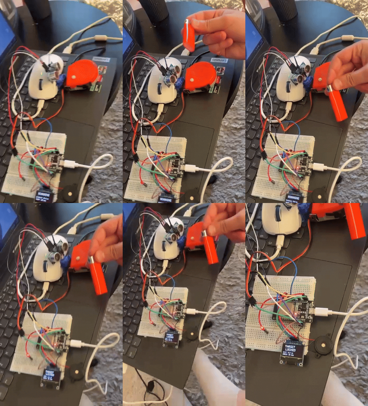
The SG90 servo rotates the HC-SR04 across the configured scan range.
The OLED displays the current:
Example:
SCANNING

Distance: 82.4 cm
Angle: 72 degWhen the measured distance drops below the detection threshold, the system does not immediately trigger the alarm.
The target must be detected for three consecutive measurements.
This reduces false triggering caused by individual noisy readings.
After three consecutive detections:
TARGET LOCKED.Example:
TARGET
LOCKED

DIST: 24.7 cm
ANGLE: 117 degWhile locked, the system continues measuring the target distance.
If the target remains beyond the loss threshold for three consecutive measurements:
The system therefore operates continuously:
SCAN
  ↓
TARGET DETECTED
  ↓
TARGET LOCKED
  ↓
ALARM
  ↓
TARGET LOST
  ↓
RESUME SCAN| Component | Function |
|---|---|
| ESP32-WROOM-32 | Main microcontroller |
| HC-SR04 | Ultrasonic distance measurement |
| SG90 Servo | Rotates the ultrasonic sensor |
| 0.96" SSD1306 OLED | Displays state, distance and angle |
| Red LED | Visual alarm indicator |
| 1 kΩ Resistor | LED current limiting |
| Passive Buzzer | Audible alarm |
| Component | ESP32 GPIO |
|---|---|
| HC-SR04 TRIG | GPIO 5 |
| HC-SR04 ECHO | GPIO 4 |
| SG90 Signal | GPIO 18 |
| OLED SDA | GPIO 21 |
| OLED SCL | GPIO 22 |
| Buzzer | GPIO 25 |
| Red LED | GPIO 26 |
Hardware note: The HC-SR04 ECHO output can exceed the ESP32's 3.3 V GPIO logic level. A proper voltage divider or level-shifting stage is recommended for a production-ready version.
The firmware was developed using the Arduino framework for ESP32.
ESP32Servo
Adafruit GFX Library
Adafruit SSD1306
WireESP32-Smart-Target-Detection-System/
│
├── Firmware/
│ └── Target Lock Radar System.ino
│
├── Hardware/
│ ├── ESP32_Radar_System.kicad_pro
│ ├── ESP32_Radar_System.kicad_sch
│ └── ESP32_Radar_System.kicad_pcb
│
├── Images/
│ ├── schematic.png
│ ├── pcb-layout.png
│ └── pcb-3d.png
│
├── Media/
│ └── media.gif
│
├── gerbers/
│ ├── ESP32_Radar_System-F_Cu.gbr
│ ├── ESP32_Radar_System-B_Cu.gbr
│ ├── ESP32_Radar_System-F_Mask.gbr
│ ├── ESP32_Radar_System-B_Mask.gbr
│ ├── ESP32_Radar_System-F_Paste.gbrThe PCB was designed in KiCad using a complete schematic-to-PCB workflow:
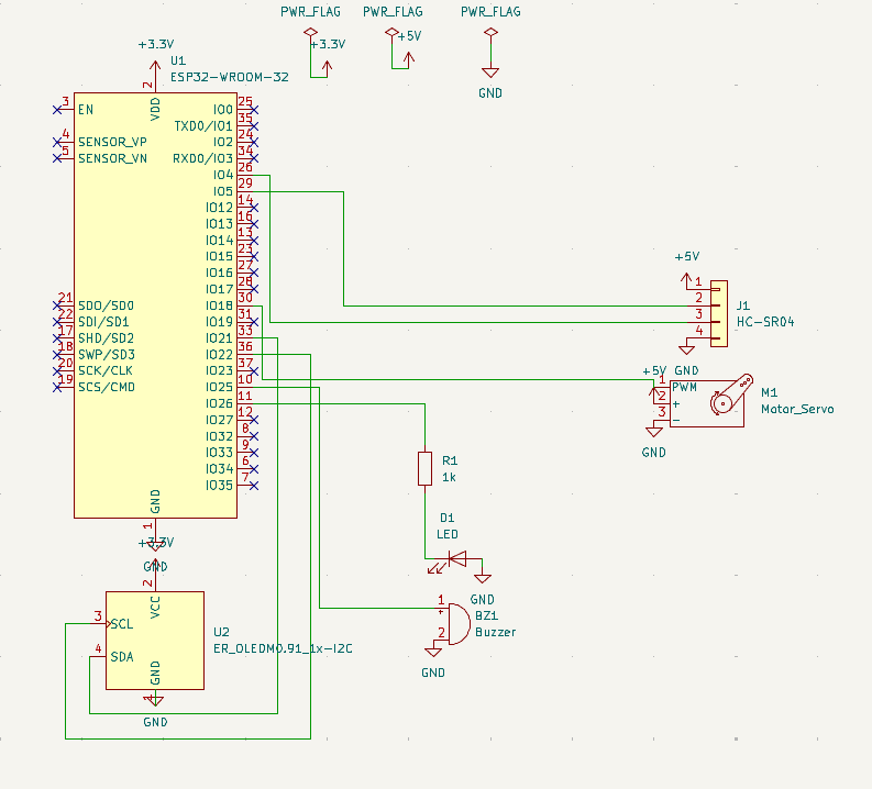
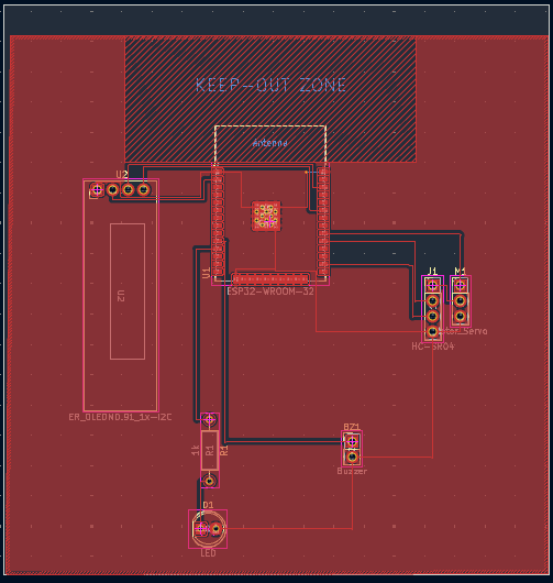
Current firmware parameters:
Scan range:              30° – 150°
Detection threshold:     35 cm
Target loss threshold:   45 cm
Detection confirmation:  3 consecutive readings
Loss confirmation:       3 consecutive readings
Scan step:               3°
These parameters can be modified directly in the Arduino firmware.
Connect the components according to the KiCad schematic:
Hardware/ESP32_Radar_System.kicad_schOpen the Arduino sketch from:
Firmware/Target Lock Radar System.inoInstall the required libraries, select the appropriate ESP32 board, and upload the firmware.
The firmware uses an SSD1306 I²C OLED with the default I²C address:
0x3CAfter startup, the system begins scanning automatically.
Production Gerber and drill files generated from the KiCad PCB are available in:
gerbers/The folder contains the required copper, solder-mask, silkscreen, board-outline, and drilling data for PCB fabrication.
This project uses a single-axis ultrasonic scanning architecture.
The HC-SR04 measures distance along the direction in which it is currently pointing. The system performs target detection and angular lock, but it does not perform camera-based object classification or continuous visual tracking.
The project was built to demonstrate practical embedded-system concepts including:
Possible extensions include:
This project is released under the MIT License.
See LICENSE for the full license text.
Developed as an ESP32 embedded-systems and PCB-design project.
ESP32 + HC-SR04 + SG90 + SSD1306 + Buzzer + LED
A compact prototype for ultrasonic target detection, angular locking, visual indication, audible alarm, and automatic scan recovery.
| Qty | Value | Footprint | References |
|---|---|---|---|
| 1 | 1k | Resistor_THT:R_Axial_DIN0207_L6.3mm_D2.5mm_P10.16mm_Horizontal | R1 |
| 1 | Buzzer | Connector_PinHeader_2.54mm:PinHeader_1x02_P2.54mm_Vertical | BZ1 |
| 1 | ER_OLEDM0.91_1x-I2C | Display:ER_OLEDM0.91_1x-I2C | U2 |
| 1 | ESP32-WROOM-32 | RF_Module:ESP32-WROOM-32 | U1 |
| 1 | HC-SR04 | Connector_PinHeader_2.54mm:PinHeader_1x04_P2.54mm_Vertical | J1 |
| 1 | LED | LED_THT:LED_D5.0mm | D1 |
| 1 | Motor_Servo | Connector_PinHeader_2.54mm:PinHeader_1x03_P2.54mm_Vertical | M1 |
c-lydia/ESP-ROS2
A tiny robot with IMU (MPU5060) and an ultrasonic sensor (HC-SR04), running on micro-ROS, communicating over UDP.

CITROMOSEPER/4-zone-irrigation-system-2026-TDK-Project
Négyzónás, ESP32-alapú adatvezérelt öntözőrendszer: érzékelők és időjárás-előrejelzés alapján dönt a vízadagról, három üzemmóddal, telefonos webes felülettel és biztonsági réteggel. TDK-projekt, Óbudai Egyetem, 2026.

Faizul6/sensor-fusion-module
A miniaturized multi-sensor module that combines distance, motion, vibration, and light sensing into a single environment-awareness output — designed and documented like a real inspection-robot sensor module…


kennySzhucheng/EnvMonitor
🌡️ 智能环境监测站 | STM32F103C8T6 + FreeRTOS + ESP8266 | 温湿度/光照/测距/OLED菜单/ThingSpeak上云 | 从裸机到RTOS到KiCad PCB全流程


NikolaiRadke/Noko_2
The do-it-yourself Arduino-based Noko monster. Version 2 with PCB and 3D printed casing.
It measures 90 × 94 mm and has 2 copper layers, 1.6 mm thick.
7 parts, built around the ESP32-WROOM-32 and HC-SR04. The full list of its parts is on this page, with links to each part's symbol and footprint where PCBKit's library has them.
From the yagiz-bas/ESP32-Smart-Target-Detection-System repository on GitHub, at the commit this page was made from: the board is Hardware/ESP32_Radar_System.kicad_pcb and its schematic Hardware/ESP32_Radar_System.kicad_sch. PCBKit opens the board in the browser, with nothing to install.
Its repository states no licence, so its author keeps all rights: ask yagiz-bas before reusing the design.