2 layers50.8 × 50.8 mm
SolarDataLogger PCB
Lopfi/solar-logger
This is a simple box with an ESP32 with a LC12S, build to replace a DataBox24G from All of Solar, which communicates with a solar inverter to collect data on power generation.
25 parts4

 xventus/Elesense-Light-Bar1
Elesense Light Bar hacked like LAMP
Esp lamp is an open-source printed circuit board by xventus, from the xventus/Elesense-Light-Bar repository on GitHub. It is a 2-layer board of 40 × 60 mm with 45 parts on 56 nets, routed with 319 tracks and 74 vias.
It is built around the ESP32-WROOM-32, LC12S and AMS1117-3.3. Its parts include 16 resistors, 11 capacitors, 5 connectors, 4 switches and 3 ICs. It belongs with the lEDs and displays boards and the ESP32 boards of this library.


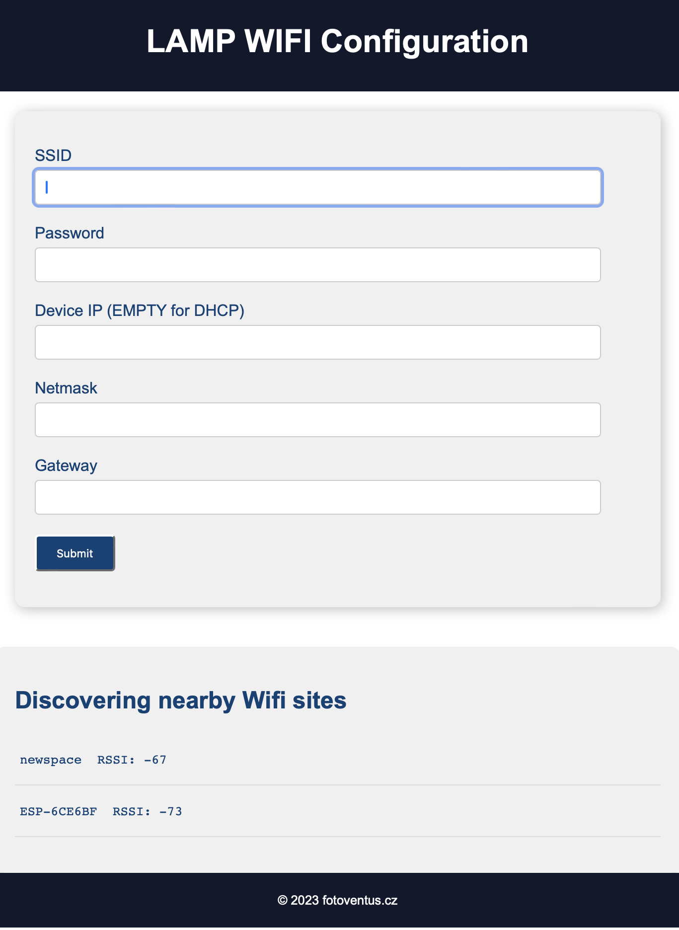
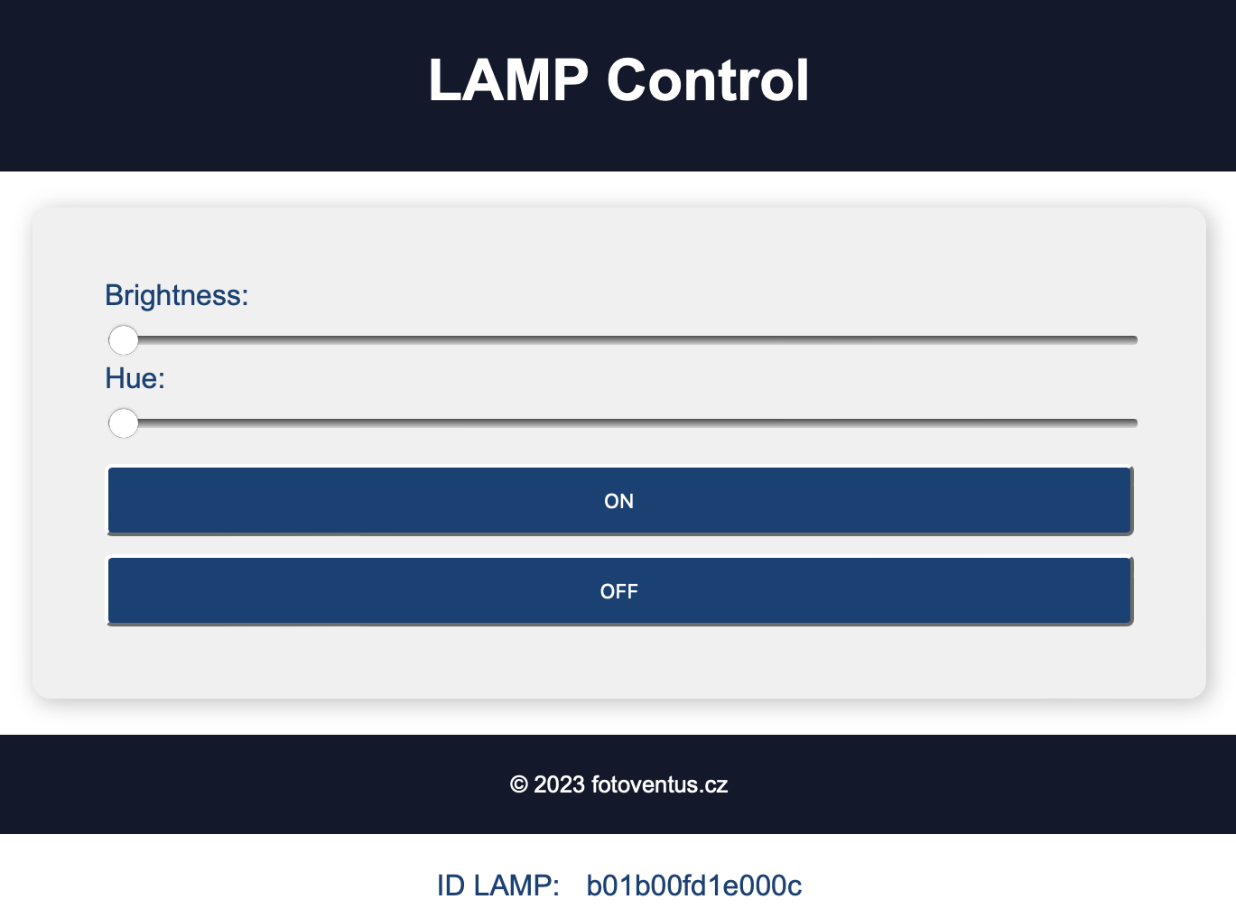
Elesense Light Bar is a monitor lamp from kickstarter. Because of the need to control it using a web interface or script and also out of curiosity how it works, this project was created. Take a screwdriver and an anlyzer and see how it works.....
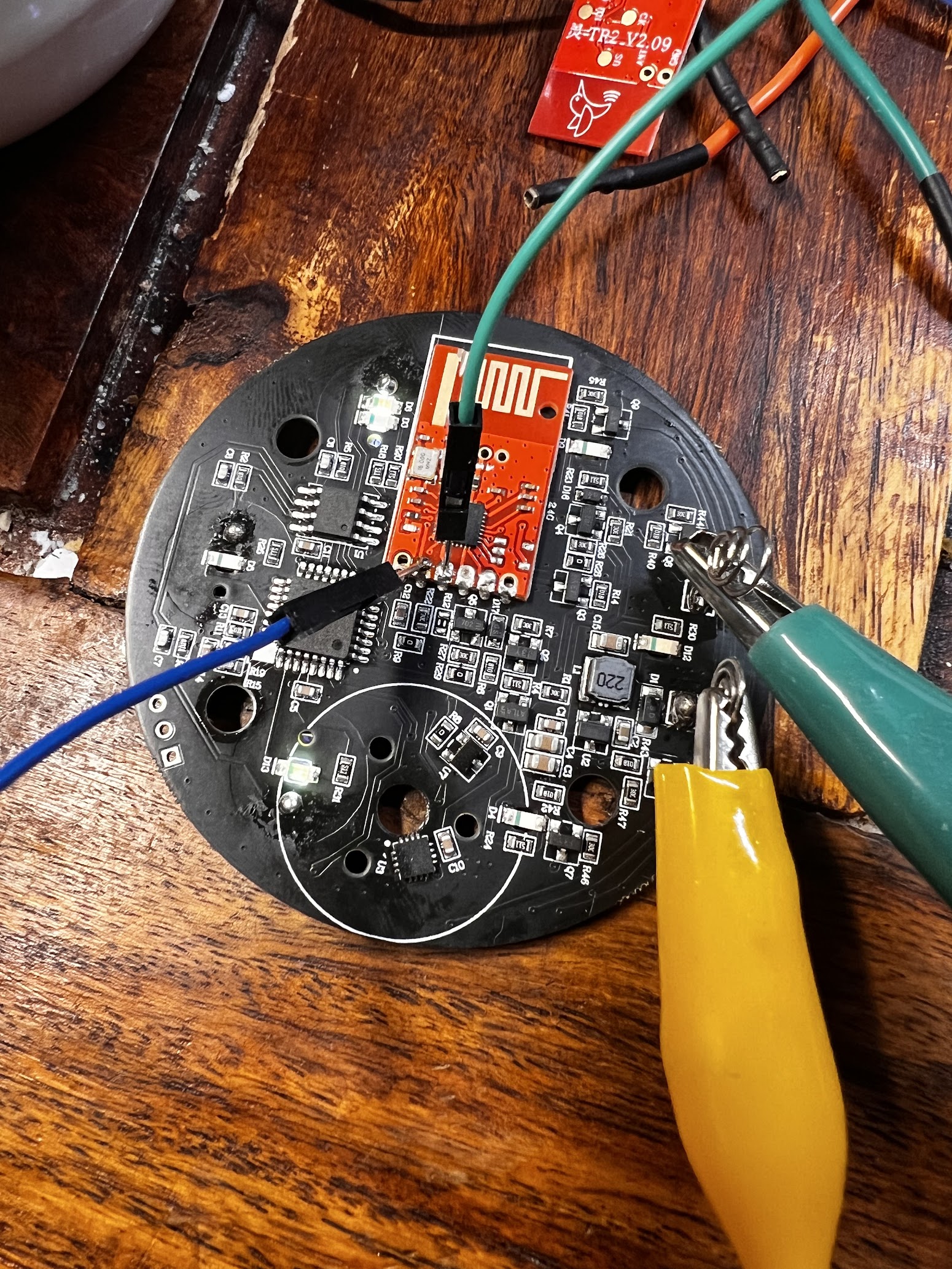 | 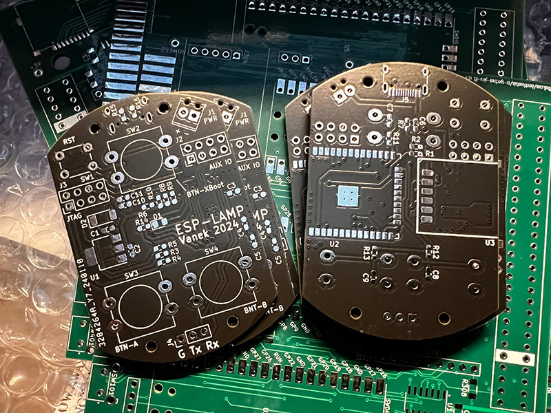 | 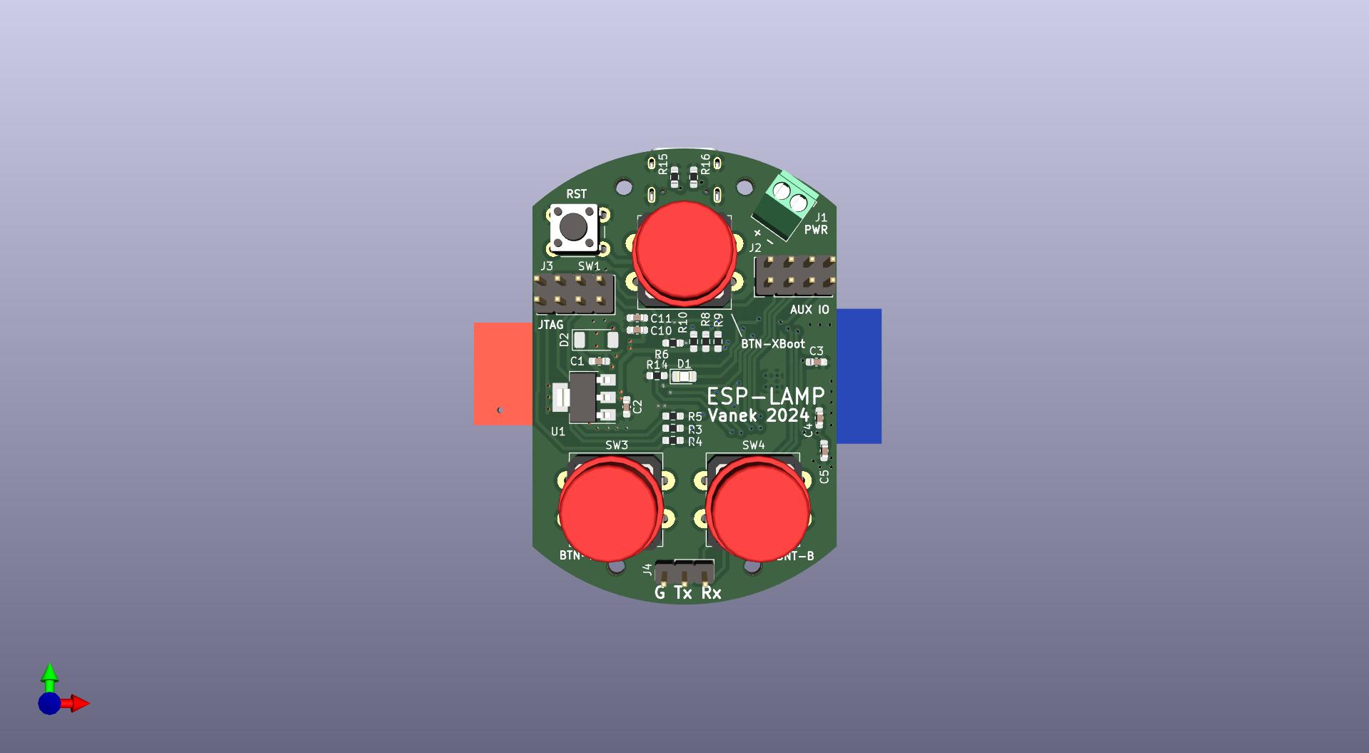 | 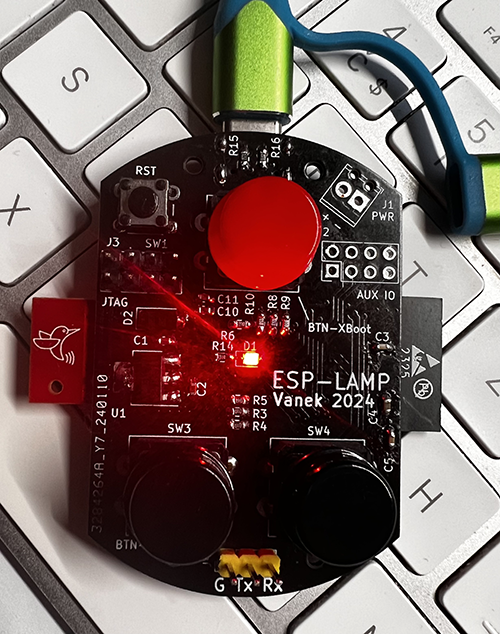 |
For communication is to use LC12S module communicating on 2.4GHz. It is used as a transparetic serial line at 9600bps. For the control of the LAMP project the ESP32 module is used. The development was based on ESP-WROVER-KIT.
Wiring the lamp controller based on ESP32
The first version of the board is made. Gerber is in the hw directory.
Still in development, custom PCB is being created, will be published in time.
| ESP32 GPIO | Note |
|---|---|
| GPIO_NUM_25 | LSC12S TX |
| GPIO_NUM_26 | LSC12S RX |
| GPIO_NUM_19 | LSC12S SET |
| GPIO_NUM_18 | LSC12S CS |
| GPIO_NUM_2 | A BUTTON |
| GPIO_NUM_4 | B BUTTON |
| GPIO_NUM_0 | FLASH BUTTON |
| GPIO_NUM_5 | HEART BEAT LED |

example:
0x53 0xC2 0x1C 0x00 0x9D 0x1B 0x00 0x0E 0x01 0x17 0x0E 0x26 0x00
| Byte position | Note |
|---|---|
| 0 | header (always 0x53) |
| 1 | lampID-1 (0xC2) |
| 2 | lampID-2 (0x1C) |
| 3 | lampID-3 (always 0x00) |
| 4 | lampID-4 (0x9D) |
| 5 | lampID-5 (0x1B) |
| 6 | lampID-6 (always 0x00) |
| 7 | lampID-7 (0x0E) (if 0xA4 appears then the rest of the octet is 0x00) |
| 8 | command 0x01 - ON, 0x10 - OFF, 0x02 - Automatic dimming (0x01) |
| 9 | 0x00 - 0x17 intensity (0x00 - min intensity, 0x17 - max intensity), note: when off 0x10 (0x17) |
| 10 | 0x00 - 0x17 intensity (0x00 - Yellow MAX, 0x17 - Yellow Min), note: when off 0x10 ([0x0E) |
| 11 | Checksum = Sum of [8] + [9] + [10] (0x26) |
| 12 | END mark (always 0x00) |
LAMP OFF command
curl -X POST -H "Content-Type: application/json" -d '{"command": "OFF"}' http://xxx.xxx.xxx.xxx/command
LAMP ON with intensity and hue command
curl -X POST -H "Content-Type: application/json" -d '{"command": "ON","brightness":"17","hue":"12"}' http://xxx.xxx.xxx.xxx/command
LAMP get ID & values
curl http://192.168.2.222/values
| Button | Note |
|---|---|
| X-BOOT + reset | Upoad firmware via serial |
| X-BOOT | ON / OFF |
| A | Increasing the brightness intensity |
| B | Decreasing the brightness intensity |
| A + B + reset | New initialization, creates a LAM AP and allows you to set up a new WiFi connection |
Note!!: Resistor R10 is used on GPIO2, it is necessary to ground it during upload. Press the push button or insert the shorting jumper on the push button.
| LED | Note |
|---|---|
| .. .. .. | LAMP runs in AP mode and waits for configuration |
| . - . - | The LAMP is waiting to be paired. Please use the original control for the lamp. ESP-LAMP will copy the lamp ID. |
| - - - - | LAMP connected to wifi and works |
| . . . . . | Error |
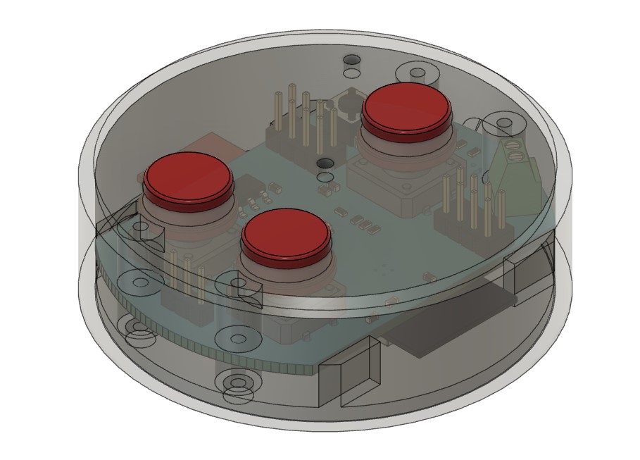 | 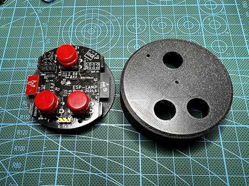 | 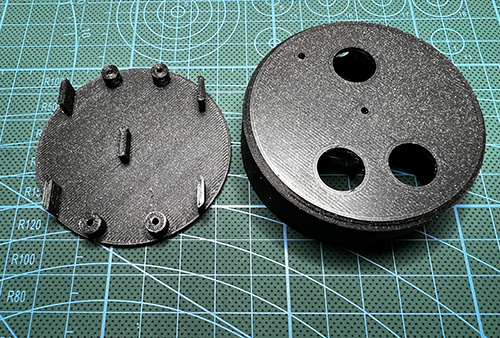 | 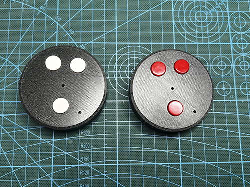 |
STL files to download for 3D printing of the box. Thanks to Pavel Vanek
| Qty | Value | Footprint | References |
|---|---|---|---|
| 6 | 100 | Resistor_SMD:R_0603_1608Metric_Pad0.98x0.95mm_HandSolder | R2, R3, R4, R5, R6, R14 |
| 4 | 1nF | Capacitor_SMD:C_0603_1608Metric_Pad1.08x0.95mm_HandSolder | C6, C7, C8, C9 |
| 4 | 470 | Resistor_SMD:R_0603_1608Metric_Pad0.98x0.95mm_HandSolder | R7, R11, R12, R13 |
| 4 | 6k8 | Resistor_SMD:R_0603_1608Metric_Pad0.98x0.95mm_HandSolder | R1, R8, R9, R10 |
| 2 | 100nF | Capacitor_SMD:C_0603_1608Metric_Pad1.08x0.95mm_HandSolder | C3, C11 |
| 2 | 10uF | Capacitor_SMD:C_0603_1608Metric_Pad1.08x0.95mm_HandSolder | C4, C10 |
| 2 | 22uF | Capacitor_SMD:C_0603_1608Metric_Pad1.08x0.95mm_HandSolder | C1, C2 |
| 2 | 5k1 | Resistor_SMD:R_0603_1608Metric_Pad0.98x0.95mm_HandSolder | R15, R16 |
| 1 | 100n | Capacitor_SMD:C_0603_1608Metric_Pad1.08x0.95mm_HandSolder | C5 |
| 1 | 1N4148 | Diode_SMD:D_SOD-128 | D2 |
| 1 | A | Button_Switch_THT:SW_PUSH-12mm_Wuerth-430476085716 | SW3 |
| 1 | AMS1117-3.3 | Package_TO_SOT_SMD:SOT-223-3_TabPin2 | U1 |
| 1 | B | Button_Switch_THT:SW_PUSH-12mm_Wuerth-430476085716 | SW4 |
| 1 | ESP32-WROOM-32 | RF_Module:ESP32-WROOM-32 | U2 |
| 1 | Expand | Connector_PinHeader_2.54mm:PinHeader_2x04_P2.54mm_Vertical | J2 |
| 1 | JTAG | Connector_PinHeader_2.54mm:PinHeader_2x04_P2.54mm_Vertical | J3 |
| 1 | LC12S | lcs:LC12S | U3 |
| 1 | LED | LED_SMD:LED_0805_2012Metric_Pad1.15x1.40mm_HandSolder | D1 |
| 1 | RESET | Button_Switch_THT:SW_PUSH_6mm_H4.3mm | SW1 |
| 1 | Screw_Terminal_01x02 | TerminalBlock_Phoenix:TerminalBlock_Phoenix_MPT-0,5-2-2.54_1x02_P2.54mm_Horizontal | J1 |
| 1 | Serial | Connector_PinHeader_2.54mm:PinHeader_1x03_P2.54mm_Vertical | J4 |
| 1 | USB_C_Receptacle_USB2.0 | Connector_USB:USB_C_Receptacle_HRO_TYPE-C-31-M-12 | J5 |
| 1 | X-BOOT | Button_Switch_THT:SW_PUSH-12mm_Wuerth-430476085716 | SW2 |
The 41 most common of 45 parts.
Lopfi/solar-logger
This is a simple box with an ESP32 with a LC12S, build to replace a DataBox24G from All of Solar, which communicates with a solar inverter to collect data on power generation.

mcauser/LC12S-Breakout
Breakout board for the LC12S 2.4GHz UART transceiver module


Hasenpups/WLED_ESP32_Controller
This work is licensed under a [Creative Commons Attribution-NonCommercial-ShareAlike 4.0 International License][cc-by-nc-sa].


nuclearcat/ESP32ETH
Simple ESP32 with native ethernet using LAN8720 phy, Arduino compatible

larryqiann/AP1512HH-ESP32
Coway AP1512HH Main Board replacement with ESP32
It measures 40 × 60 mm and has 2 copper layers, 1.6 mm thick.
45 parts, built around the ESP32-WROOM-32, LC12S and AMS1117-3.3. The full list of its parts is on this page, with links to each part's symbol and footprint where PCBKit's library has them.
From the xventus/Elesense-Light-Bar repository on GitHub, at the commit this page was made from: the board is hw/esp-lamp.kicad_pcb and its schematic hw/esp-lamp.kicad_sch. PCBKit opens the board in the browser, with nothing to install.
Its repository states no licence, so its author keeps all rights: ask xventus before reusing the design.