Allows USB printing to Panasonic KX-R/RK-T/RK-H typewriters, KX-W word processors, and KX-W55 printer. Emulates KX-R60 (working) and RP-K100/RP-K105 (in development) interface adapters
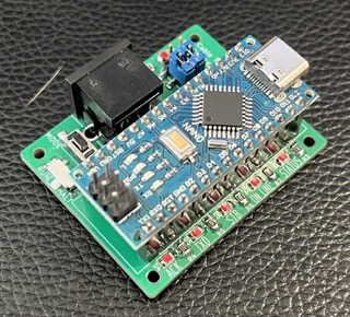
Panasonic typewriter interface v2 is an open-source printed circuit board by xunker, from the xunker/panasonic_typewriter_interface repository on GitHub, published under the GPL-3.0 licence. It is a 2-layer board of 57.2 × 45.5 mm with 49 parts on 61 nets, routed with 487 tracks and 24 vias.
It is built around the KMDGX-8S-AS. Its parts include 15 resistors, 15 diodes, 9 connectors, 2 switches and 1 fuse. It belongs with the interfaces and adapters boards and the AVR (ATmega, ATtiny) boards of this library.
Print text using the Interface Port of your compatible Panasonic KX-R Daisywheel
typewriter, KX-W word processor, RK-T "CupWheel" typewriter, or KX-WD55
daisywheel printer. Emulates the serial/RS-232 function of the KX-R60 (currently
working), and RP-K100/RP-K105 (in development) interface adapters.
Use your 🏋️heavy🥌 and 🐢slow🐌 typewriter as a noisy, inconvenient, inflexible,
single-page printer!
A complete video of the high low-speed daisywheel action can be found on the TouYubes.
Developed and tested with my KX-R435, and should be compatible with any other
Panasonic typewriter with the round, 8-pin MiniDIN port.
KX-W series with DE-9 port
Untested, but should work with machines which have a DE-9 (DB-9) connector.
Currently does not work, but is in active development. See
rp-k10x_vs_kx-r60.md for research details.
Typewriter Pinout
See PINOUT.md for detailed information about the typewriter
connector pinout.
Arduino Wiring
Although this is built around the Arduino Nano, any 5V board which uses the
ATmega328 will also work. Any other 5V ATmega MCU should work as as well (such
as the ATmega32U4in the Arduino Micro), and clones like the LGT8F328 (tested).
Non-ATmega/AVR boards may work, as long as they are compatible with the
libraries used in this project (see "Required Libraries"), have enough pins,
and run on 5V (or are 5V-tolerant). I have not tried any of this.
Adapter Board
There's an adapter board available to ease assembly,
and to provide additional features.
Connecting Arduino to Typewriter without Adapter Board
Minimum required:
Arduino Pin
Goes To
Purpose
A0
Typewriter ON_LINE pin
~ON_LINE signal to typewriter
A1
Typewriter TXD_PIN pin
TXD_PIN signal to typewriter
A2
Typewriter STB_PIN pin
~STB_PIN signal to typewriter
A3
Typewriter ACK_PIN pin
~ACK_PIN signal from typewriter
A6
Switch to ground
"RUN/HALT" switch (GO_PIN), active low
Optional "Mode" button:
Arduino Pin
Goes To
Purpose
A7
Button to ground
Mode button (MODE_PIN), optional, active low
Separate USB-to-Serial Adapter: You can use the built-in USB port as the Serial
connection, but hardware flow control will not be available. To use hardware
flow control you will need to connect up to an external USB to Serial adapter:
Arduino Pin
Goes To
Purpose
TX1 (D1)
RxD on USB Serial Module
Transmit serial data to USB host
RX0 (D0)
TxD on USB Serial Module
Receive serial data from USB host
11
CTS on USB Serial module
CTS (Clear to Send)
12
RTS on USB Serial module
RTS (Request to Send)
You can also connect some optional additional LEDs for debugging (or because
they look neat when they blink):
Arduino Pin
Goes To
Purpose
8
LED +
State of ON_LINE pin
6
LED +
State of STB_LED pin
2
LED +
State of ACK_LED pin
3
LED +
State of TXD_LED pin
Code
The included code will read data from the Serial device (usually USB Serial)
and relay that to the typewriter in the correct format.
Required Libraries
The following libraries are required by default. They can either be installed
manually or via the Arduino IDE:
SerialCmd and MemoryUsage are only needed by the
Serial Configuration Terminal (enabled default). AceButton
is only needed if the "Mode" button is enabled (enabled by default).
Configure
NOTE: if you are using the included adapter board, you do not need to do any
additional configuration. Simply connect your cable and adjust the "Cable Type"
jumpers so they are both closest to whichever LED (D1 or D2) is lit up.
#define ON_LINE_PIN A0 // Output, active LOW
#define STB_PIN A2 // Output, active LOW
#define ACK_PIN A3 // Input, active LOW
#define TXD_PIN A1 // Output; HIGH = 1, LOW = 0
#define GO_PIN A6 // trigger printing to begin when this is pulled low
#define MODE_PIN A7 // trigger printing to begin when this is pulled low/* RTS_PIN/CTS_PIN are only needed if `#define ENABLE_RTS_CTS` is uncommented */
#define RTS_PIN 12// incoming from RTS, active low (for ENABLE_RTS_CTS)
#define CTS_PIN 11// outgoing to CTS, active low (for ENABLE_RTS_CTS)
CHECK WHAT KIND OF CABLE YOU HAVE, and remember that a Macintosh-style printer
cable likely has several pins swapped.
Once you're done, upload it to your Arduino-compatible MCU.
There is also a "Demo Mode" that will just print text automatically and not
wait for input over serial; enable that by uncommenting // #define TEST_MODE
in panasonic_typewriter_interface.ino.
Extra LEDs (Optional, default)
By default, there are 4 addition LEDs broken out to show the status of each of
the signal lines (in addition to the built-in LED).
These LEDs will reflect the state of each respective signal.
Note, this is a logic state, not the electrical state. That means for
active-low pins like ON_LINE, STB, and ACT, a low signal will turn on the
appropriate LED.
However, if you do not require these additional LEDs you can comment-out the
line #define ENABLE_MULTIPLE_LEDS, and then only the built-in LED will be
used.
Printerering (aka, how to use this)
Once the code is uploaded and your Arduino is properly connected to your
typewriter, turn on your typewriter and load paper as appropriate.
Set Typewriter to "On-Line Mode"
Then, you must get in to "On-Line Mode". The command varies from model to model,
so consult the owners manual for more detail. In the case of the KX-R435, you
enter On-Line Mode by holding down the CODE key and then pressing E; the LCD
should now say "On-Line Mode". To exit On-Line mode, or to stop printing, press
CODE+E again.
Set microcontroller to "RUN" Mode
Once in "On-Line Mode", you'll need to set your Arduino to "Run" mode. If you
are using the included adapter board, you do this by
switching the "RUN/HALT" switch to "RUN". If you are have wired your own
microcontroller, you will connect pin A7 (or whatever pin you assigned to
GO_PIN) to ground.
Once you switch to "RUN" mode, reset the microcontroller once to ensure it's now
in the correct mode.
As long as that pin is grounded, sentences will keep being sent to the
typewriter.
Send text - SLOWLY
Finally, open a serial connection to your MCU (using the built-in Serial Console
in the Arduino IDE works well).
The default speed is 300 baud. Yes, you read correctly, 300 baud. Because
it's a freakin' TYPEWRITER! It can barely keep up with 30 char/sec. If you
want a laser printer, you know where to find one.
Out of the box, the Arduino toolchain only gives the atMega328 a 64 byte serial
buffer, which can hold about 2 seconds of data at 300 baud. I'd actually like
to set the default speed to 110 baud, but no operating systems have supported
that speed for at least 30 years. Yes, not even Linux despite the lies that
stty tells you.
Send some text! With luck, you'll see it appear in your paper! Eventually!
Can't keep up with 300 baud without hardware flow control
The default speed is 300 baud (see "Send text - SLOWLY" for reasons), and even
that has problems unless you use hardware flow control (RTS/CTS) and text will
start to be dropped in about 2 lines.
This is because of two things issues:
the Arduino Serial buffer is
only 64 bytes,
on the ATmega328
Even the fastest Panasonic Daisywheels can only print 15 characters/sec, which is
only half the speed of 300 baud, and most models can only print 12 CPS
There are two solutions:
Use hardware flow control
On USB, this requires use of a separate USB-to-Serial adapter because the
IC included on Arduino Nano does not connect any lines besides TxD, RxD,
and DTR
The current Adapter Board can use a separate USB-to-Serial adapter connected
to J4, with CTS connexted to "TX1" and RTC connected to "RX1"
Future versions of the adapter board will include footprints for a separate
USB-to-serial converter
add a "character delay" when you send, greater than 30ms/character
CoolTerm can do this: Options->Transmit->Use Transmit Character Delay
Reboot required when switching from from HALT to RUN with Serial Console
If Serial Console support is compiled in (the default), a reboot (via reset
button) is require when going from HALT mode to RUN mode.
Mode button doesn't do anything
The "Mode Button" is currently GN/DN (goes nowhere & does nothing).
Allows USB printing to Panasonic KX-R/RK-T/RK-H typewriters, KX-W word processors, and KX-W55 printer. Emulates KX-R60 (working) and RP-K100/RP-K105 (in development) interface adapters
Allows USB printing to Panasonic KX-R/RK-T/RK-H typewriters, KX-W word processors, and KX-W55 printer. Emulates KX-R60 (working) and RP-K100/RP-K105 (in development) interface adapters
How big is the Panasonic typewriter interface v2 PCB?
It measures 57.2 × 45.5 mm and has 2 copper layers, 1.6 mm thick.
What parts does the Panasonic typewriter interface v2 use?
49 parts, built around the KMDGX-8S-AS. The full list of its parts is on this page, with links to each part's symbol and footprint where PCBKit's library has them.
Where can I download the Panasonic typewriter interface v2 KiCad files?
From the xunker/panasonic_typewriter_interface repository on GitHub, at the commit this page was made from: the board is adapter_boards/panasonic_typewriter_interface_v2/panasonic_typewriter_interface_v2.kicad_pcb and its schematic adapter_boards/panasonic_typewriter_interface/panasonic_typewriter_interface.kicad_sch. PCBKit opens the board in the browser, with nothing to install.
Can I use the Panasonic typewriter interface v2 design in my own project?
Its repository publishes it under the GPL-3.0 licence: you may reuse it on that licence's terms (keep the author's notice, and for a copyleft licence share your changes alike).